

Motor-driven lifting and pressing and thread trimming mechanism for button attaching machine
A wire-cutting mechanism and a machine-motor technology, applied in the field of button-stitching machines, can solve the problems of large suction force of electromagnets, easy gaps in connecting parts, and large impact of related connecting parts, etc., and achieves convenient operation, simple structure, and extended force arm. Effect
- Summary
- Abstract
- Description
- Claims
- Application Information
AI Technical Summary
Problems solved by technology
Method used
Image

Examples
Embodiment 1
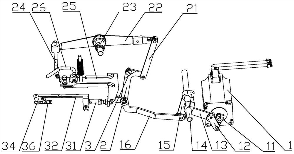
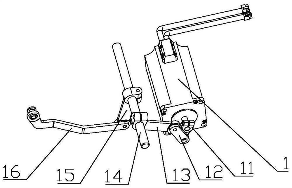
[0034] Embodiment one: contrast with attached figure 1 And attached figure 2 , a thread lifting mechanism driven by a button sewing machine motor, the output shaft of the motor 1 is connected with a driving rod 2 for lifting, pressing and cutting through a transmission assembly, and the driving rod 2 for lifting, pressing and cutting is hinged on a fixed rotation axis On the screw 3, one end of the lifting and trimming drive rod 2 is connected with a lifting component, and the other end is connected with a trimming component. The rotary shaft screw 3 rotates in different directions, and drives the action of lifting the pressure and cutting the line and the action of reset respectively.
[0035] Control attached Figure 7 And attached Figure 8 , the pressure-lifting and cutting-line driving rod 2 is a reverse Z-shaped rod, and the connection structure with other components is: the transmission component and the wire-cutting component are both hinged at the lower end of the...
Embodiment 2
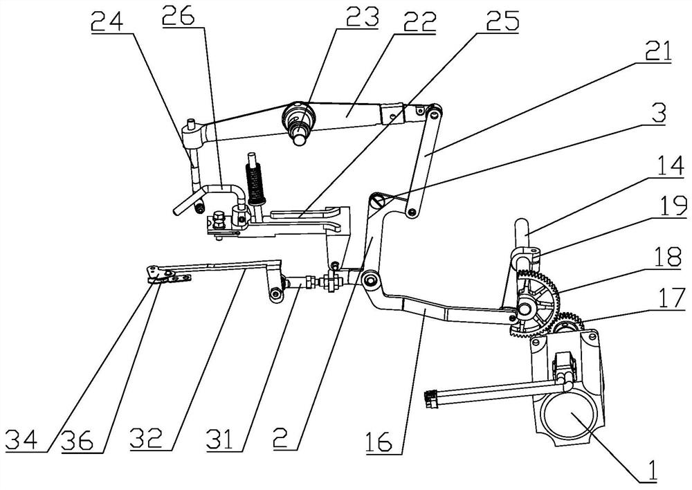
[0043] Embodiment two: contrast with attached image 3 And attached Figure 4 , the present invention also provides another transmission assembly, including: a driving gear 17 fixed on the motor shaft, the driving gear 17 meshing with a driven gear 18 fixed on the transmission shaft 14, the transmission shaft 14 Also be fixed with transmission crank 19, described transmission crank 19 is hinged with one end of transmission connecting rod 16, and the other end of transmission connecting rod 16 is hinged with lifting pressure trimming driving rod 2. The other components in the second embodiment, such as the pressure-lifting and thread-cutting driving rod 2, the lifting-pressing assembly and the thread-cutting assembly, are the same as those in the first embodiment.
[0044] The driving gear 17 is fixed on the end of the motor shaft, the driven gear 18 is fixed on the end of the transmission shaft 14 , and there is a gap between the driving crank 19 and the driven gear 18 .
[...
PUM
 Abstract
Description
Claims
Application Information