Unmanned aerial vehicle automatic hangar

An unmanned aerial vehicle and automatic technology, applied in the field of unmanned aerial vehicles, can solve problems such as error-prone efficiency, and achieve the effect of simple and fast deployment, convenient transportation operations, and space saving

Active Publication Date: 2020-12-08
成都震风航空技术有限公司
View PDF9 Cites 6 Cited by
  • Summary
  • Abstract
  • Description
  • Claims
  • Application Information

AI Technical Summary

Problems solved by technology

[0002] When performing operations, the UAV needs to be transported to the corresponding deployment location first, and then perform the corresponding operation tasks. The UAVs in the prior art need to be manually operated after arriving at the destination through the traditional hangar calculation to realize the unmanned operation. The operation of drones requires a lot of manual participation in the operation tasks of drones, which is prone to errors and low efficiency

Method used


Image

  • Unmanned aerial vehicle automatic hangar
  • Unmanned aerial vehicle automatic hangar
  • Unmanned aerial vehicle automatic hangar

Examples


Embodiment 1

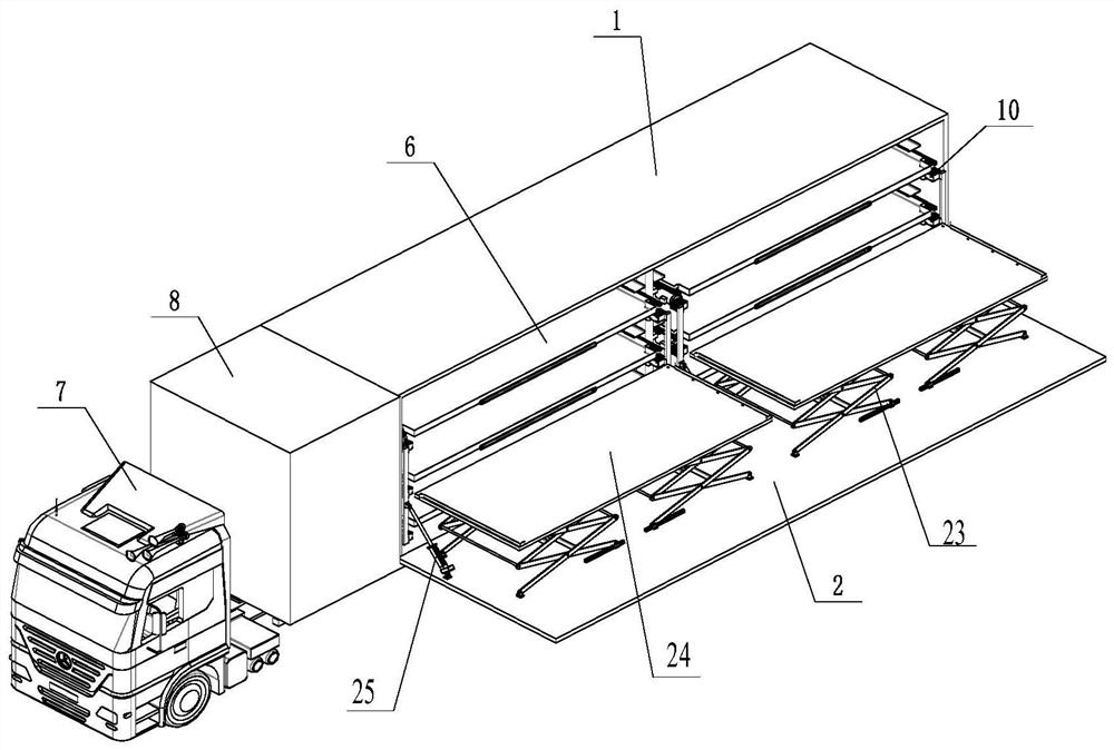
[0065] Please refer to figure 1 and Figure 4 , an automatic hangar for unmanned aerial vehicles, the automatic hangar for unmanned aerial vehicles comprises: a movable carrier 7, a storage body 1, a storage door 2, several storage areas for unmanned aerial vehicles, several locking devices, several transplanting jacks Mechanism, wireless charging system, control system and power supply system, wherein, a number of unmanned aerial vehicle storage areas are arranged in the warehouse, and each unmanned aerial vehicle storage area corresponds to an unmanned aerial vehicle storage unit 6, and each unmanned aerial vehicle storage area Each is equipped with a locking device for fixing the storage unit of the UAV; the warehouse body is provided with a warehouse door, and the warehouse door is provided with a transplanting and lifting mechanism, which is used to store the UAV. The unit is taken out from the corresponding UAV storage area and the UAV storage unit is stored in the corr...

Embodiment 2

[0092] Such as Figure 5 and Figure 6 As shown in the transplanting jacking mechanism, the inner wall of the door panel 22 is provided with a jacking mechanism 23, and the end of the jacking mechanism 23 away from the door panel 22 is connected to the lifting platform 24, and the lifting platform 24 is provided with a transfer mechanism; the lifting platform 24 is used to carry the unmanned aerial vehicle ; The jacking mechanism 23 is used to make the landing platform 24 close to and away from the door panel 22 ; The bottom edge of door panel 22 is used for being hinged with hangar side; Door panel 22 inwalls are also hinged telescopic device 25, and telescopic device 25 is used for being hinged with hangar side away from an end of door panel 22. The upper surface of the lifting platform 3-24 is parallel to the inner side wall of the door panel 22; the lifting platform 24 and the jacking mechanism 23 together form a scissor lifting platform.

Embodiment 3

[0094] Such as Figure 5 to Figure 10The transplanting jacking mechanism shown, on the basis of the second embodiment, this embodiment optimizes the design of the transfer mechanism, specifically: the transfer mechanism includes a conveyor belt 26 capable of reciprocating movement, and the conveyor belt 26 is fixedly connected to the plectrum 27 ; also includes a first drive means 28 for driving the conveyor belt 26 . The first driving device 28 is a motor, and the conveyor belt 26 is a chain or a belt; the conveyor belt 26 rotates around the driving wheel 29 and the driven wheel 30, and the first driving device 28 drives the driving wheel 29 to rotate. Also comprise the 3rd slide rail 31 that is fixed on the landing platform 24, one end of the 3rd slide rail 31 stretches out to the outside of the landing platform 24, and when storehouse door is opened, this end extends toward storehouse interior direction. Also includes a mounting part 32 that is slidably connected on the th...


PUM


Abstract

The invention discloses an unmanned aerial vehicle automatic hangar, and relates to the field of unmanned aerial vehicles. A transferring jacking mechanism is used for taking out an unmanned aerial vehicle storage unit from a corresponding unmanned aerial vehicle storage area, storing the unmanned aerial vehicle storage unit into the corresponding unmanned aerial vehicle storage area, and carryingthe unmanned aerial vehicle storage unit to move; a movable carrier is used for carrying the unmanned aerial vehicle automatic hangar to move; a wireless charging system is used for wirelessly charging an unmanned aerial vehicle in the unmanned aerial vehicle storage unit; a power supply system is used for supplying power to the unmanned aerial vehicle automatic hangar; and a control system is used for controlling a garage door, a locking device, the transferring jacking mechanism, the wireless charging system and the power supply system, and automatic take-off, landing, storage and chargingof the unmanned aerial vehicle are achieved. The hangar is improved and designed, a large number of traditional workers are prevented from participating in the operation process, automatic take-off, landing, storage and charging of the unmanned aerial vehicle are achieved, the operation efficiency of the unmanned aerial vehicle is improved, and the probability of operation faults is reduced.

Description

technical field [0001] The invention relates to the field of unmanned aerial vehicles, in particular to an automatic hangar for unmanned aerial vehicles. Background technique [0002] When performing operations, the UAV needs to be transported to the corresponding deployment location first, and then perform the corresponding operation tasks. The UAVs in the prior art need to be manually operated after arriving at the destination through the traditional hangar calculation to realize the unmanned operation. The operation of drones requires a lot of manual participation in the operation tasks of drones, which is prone to errors and low in efficiency. Contents of the invention [0003] The invention provides an automatic hangar for unmanned aerial vehicles. The invention improves and designs the hangar, avoids a large number of traditional labor involved in the operation process, realizes automatic take-off, landing, storage and charging of unmanned aerial vehicles, and improv...

Claims


Application Information

Patent Timeline
Patent Type & Authority Applications(China)
IPC IPC(8): E04H6/44B64F1/22B60P3/11
CPCB60P3/11B64F1/222E04H6/44
Inventor 张海涛付伟平金小川李佳骏刘长鑫谢明建赵君君
Owner 成都震风航空技术有限公司
Why Eureka
Try Eureka