
Integrated gas mixing structure, burner and cooker

An integrated burner technology, applied to gas fuel burners, burners, combustion types, etc., can solve the problems of flue gas heat waste, insufficient burner combustion, etc., and achieve the effect of reducing external emissions and improving thermal efficiency

Active Publication Date: 2022-01-07
NINGBO FOTILE KITCHEN WARE CO LTD
View PDF5 Cites 0 Cited by
  • Summary
  • Abstract
  • Description
  • Claims
  • Application Information

AI Technical Summary

Problems solved by technology

[0004] The technical problem to be solved by the present invention is to provide an integrated gas mixing structure, a burner and a cooker in order to overcome the defects of insufficient combustion of the burner in the prior art, waste of flue gas heat and part of the insufficient combustion gas

Method used


Image

  • Integrated gas mixing structure, burner and cooker
  • Integrated gas mixing structure, burner and cooker
  • Integrated gas mixing structure, burner and cooker

Examples


Embodiment Construction

[0032] The present invention is further illustrated below by means of examples, but the present invention is not limited to the scope of the examples.

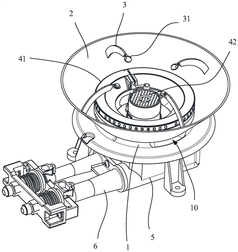
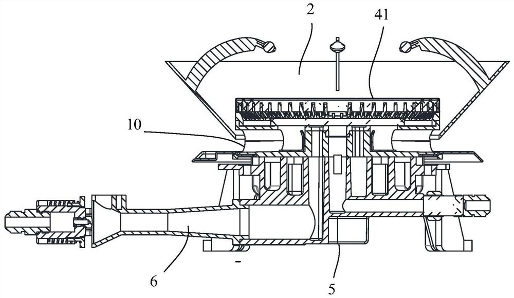
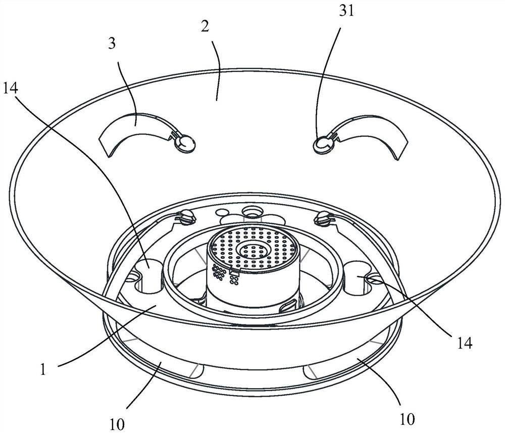
[0033] Such as Figure 1-Figure 6 As shown, the present invention discloses an integrated gas mixing structure. The integrated gas mixing structure includes a gas mixing chamber 1. A secondary air inlet 10 is arranged on the outer ring surface of the gas mixing chamber 1. The secondary air inlet 10 is connected to the mixing chamber. The outer surface and interior of the gas chamber 1. Such as Figure 1-Figure 6 As shown, the integrated air mixing structure of the present invention also includes an energy gathering cover 2, which is connected to the outer surface of the air mixing chamber 1, wherein the height of the lower edge of the energy gathering cover 2 is between the secondary air inlet 10 Between the height of the upper edge 101 and the lower edge 102 of the inlet, and in the height direction of the secondary air inl...


PUM


Abstract

The invention discloses an integrated gas mixing structure, a burner and a cooker. The integrated gas mixing structure includes: a gas mixing chamber, a secondary air inlet is provided on the outer ring surface of the gas mixing chamber, and the secondary air inlet connects the outer surface and the inside of the gas mixing chamber; Cover, the energy gathering cover is connected to the outer surface of the air mixing chamber, wherein the height of the lower end edge of the energy gathering cover is between the height of the upper edge and the lower edge of the inlet of the secondary air inlet , and form a smoke return area in the height direction of the secondary air inlet. The invention re-oxidizes the incompletely burned CO in the flue gas to CO 2 , to reduce the external emission of CO, and at the same time recover the heat in the flue gas to the bottom of the pot to improve the thermal efficiency of the burner.

Description

technical field [0001] The invention relates to an integrated gas mixing structure, a burner and a cooker. Background technique [0002] During the combustion process of the current common cooker, the flue gas produced still carries a large amount of heat, and at the same time, some of the gas in the flue gas is not fully burned, resulting in the waste of these heat and gas, making the gas use efficiency of the burner not high . [0003] In addition, usually the pan support of the cooker is placed on the panel. When the cooker is working, a large amount of heat is conducted to the panel through the pot support, which increases the risk of some cooker glass panels bursting, and the cooker also loses this part of heat. Contents of the invention [0004] The technical problem to be solved by the present invention is to provide an integrated gas mixing structure, a burner and a cooker in order to overcome the defect that the burner burns insufficiently in the prior art, and t...

Claims


Application Information

Patent Timeline
Patent Type & Authority Patents(China)
IPC IPC(8): F23D14/70F23D14/64F23D14/46F24C15/10F24C3/08F24C15/20
CPCF23D14/70F23D14/64F23D14/46F24C15/10F24C3/085F24C15/205
Inventor 吴超严力峰徐强姚青
Owner NINGBO FOTILE KITCHEN WARE CO LTD
Learn More