High-efficiency dyed cloth drying device

A drying device and high-efficiency technology, applied in drying, drying machine, drying gas arrangement, etc., can solve problems such as large spacing, easy fading of pigments, and affecting product quality, and achieve the effect of ensuring uniformity

Active Publication Date: 2020-12-08
泉州台商投资区飞翔机械设计服务中心
View PDF16 Cites 3 Cited by
  • Summary
  • Abstract
  • Description
  • Claims
  • Application Information

AI Technical Summary

Problems solved by technology

The most important thing after the dyeing is to dry the dyed cloth. This step determines the coloring of the dyed cloth. If the drying is not complete, the pigment on the dyed cloth will fade easily, which will greatly affect the product. The quality of the existing dryer is generally to support the cloth through the box through the rotating roller, and heat it through the heating tube in the box to dry. The heating tube is generally above or below the cloth, and the heating tube Make the inside of the box form a high-temperature and dry environment to realize the drying treatment of the cloth, but the distance between the heating tube and the cloth is too large, which will easily make the cloth dry unevenly

Method used


Image

  • High-efficiency dyed cloth drying device
  • High-efficiency dyed cloth drying device
  • High-efficiency dyed cloth drying device

Examples


Embodiment 1

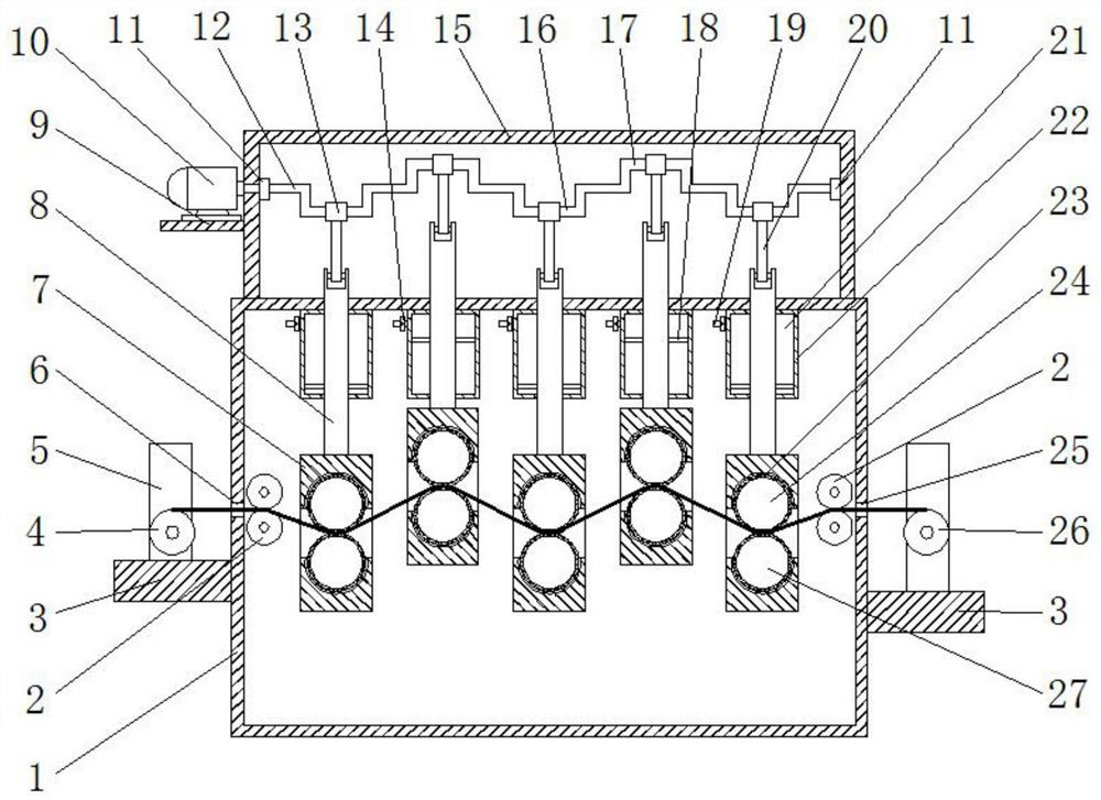
[0029] Such as figure 1 The shown high-efficiency dyeing cloth drying device includes a box body 1 with an electric heating element (not shown in the figure) inside, and two opposite sides of the box body 1 are provided with mutually aligned cloth inlets 6 and Cloth outlet 25, the side of the box body 1 corresponding to the cloth outlet 25 outlet end is provided with a winding roller 26, and the opposite side of the cloth inlet 6 and the cloth outlet 25 in the box body 1 is respectively provided with a group for conveying cloth. Conveyor roller group 2, be provided with at least two lifting frames 7 (five lifting frames 7 are shown in the accompanying drawing) equally spaced between two groups of conveying roller groups 2, described lifting frame 7 is provided with for clamping The upper roller 24 and the lower roller 27 holding the cloth, the upper roller 24 and the lower roller 27 are all parallel to the conveying roller group 2;

[0030] The top of each lifting frame 7 is ...

Embodiment 2

[0036] The difference between this embodiment and embodiment 1 is:

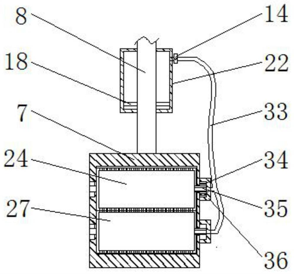
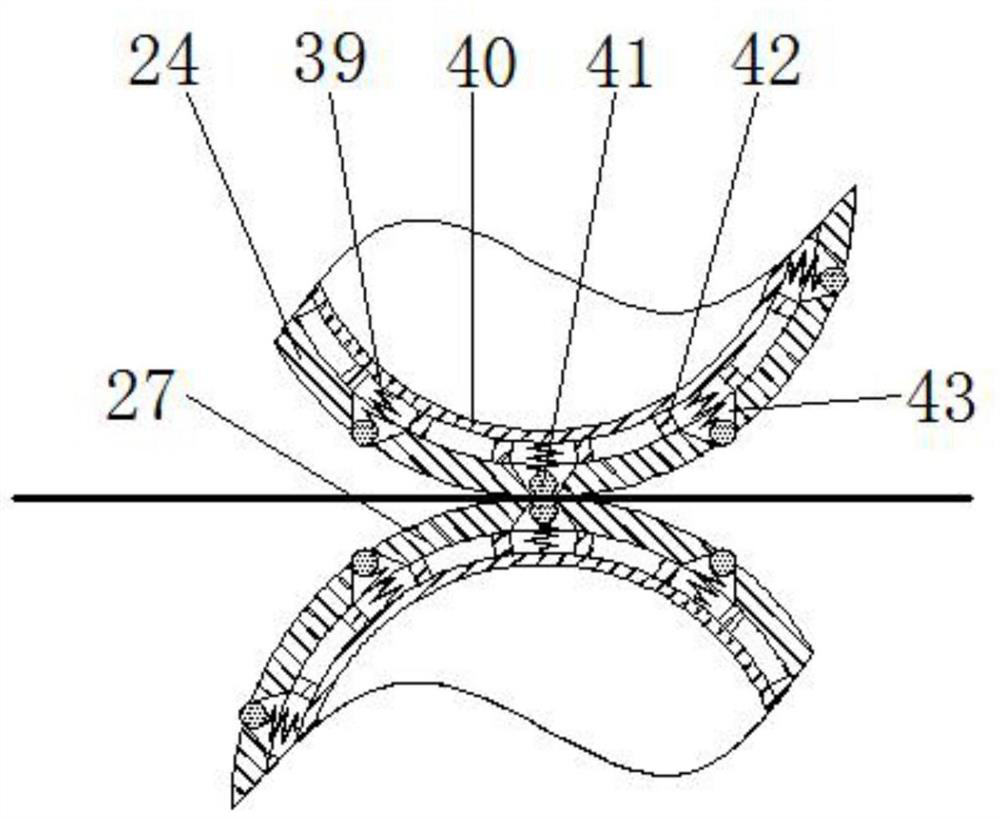
[0037] In this example, if Figure 5 and Figure 6 As shown, the first exhaust pipe 33 is only in communication with the inner cavity of the upper drum 24, not with the inner cavity of the lower drum 27, only the through hole 43 of the upper drum 24 is provided with a blocking assembly, and the lower drum No plugging assembly is provided in the through hole 43 of 27; Figure 4 As shown, a second cylinder 38 fixed to the inner bottom of the box body 1 is provided under each lifting frame 7, and a piston 31 whose periphery is attached to its inner wall is provided in the second cylinder 38. , and the rod-shaped part of the piston 31 runs through the top of the second cylinder 38 and is fixedly connected to the bottom of the lifting frame 7; the two sides of the lower end of the second cylinder 38 are respectively connected with a second air intake pipe 37 communicating with its inner cavity and the second ex...


PUM


Abstract

The invention discloses a high-efficiency dyed cloth drying device, and belongs to the field of drying equipment. The high-efficiency dyed cloth drying device comprises a box body internally providedwith an electric heating element, two or more lifting frame bodies are arranged in the box body at equal intervals, the tops of the lifting frame bodies are connected with lifting rods, and the upperends of the lifting rods are connected with a lifting driving mechanism; an upper roller and a lower roller used for clamping a cloth are arranged in each lifting frame body, through holes are evenlyspread over the side faces of the upper rollers and the lower rollers, the upper rollers communicate with a first air cylinder arranged at the top in the box body through a first exhaust pipe, the opening diameter of each through hole is gradually reduced from the inner side end to the outer side end of the through hole, and a blocking assembly used for blocking an outer port of each through holeis arranged in the through hole; and the blocking assemblies each comprise a blocking ball with the diameter between the diameter of an inner port and the diameter of the outer port of the corresponding blocked through hole, and a spring connected to the plugging ball. The high-efficiency dyed cloth drying device is high in drying treatment efficiency, good in uniformity, and capable of thoroughlydrying the cloth and treating water vapor generated in the drying process in time, only needs one power driving mechanism, is convenient to control and can save energy.

Description

technical field [0001] The invention relates to the field of drying equipment, in particular to a high-efficiency dyeing cloth drying device. Background technique [0002] The development prospect of the textile industry is very huge. The textile industry will always accompany our life and is closely related to our life. The clothes we wear all need textiles to complete. With the improvement of our country's economic level, the color of our clothes is no longer black, white and gray. All kinds of colors accompany our clothes to reflect our colorful and diverse personalities. The appearance of these clothes in various colors is attributed to the improvement of dyeing technology, which is an important step in the development of textiles, and the improvement of dyeing technology drives the development of the textile industry. The most important thing after the dyeing is to dry the dyed cloth. This step determines the coloring of the dyed cloth. If the drying is not complete, t...

Claims


Application Information

Patent Timeline
Patent Type & Authority Applications(China)
IPC IPC(8): F26B13/08F26B21/00F26B25/00F26B25/02F26B25/20B65H18/10
CPCB65H18/103F26B13/08F26B21/001F26B21/004F26B25/00F26B25/02F26B25/20
Inventor 林飞燕
Owner 泉州台商投资区飞翔机械设计服务中心
Why Eureka
Try Eureka