Image forming apparatus and computer readable storage medium storing program

A storage medium and computer technology, applied to instruments, optics, electrical recording, etc., can solve problems such as poor cleaning

Inactive Publication Date: 2020-12-08
KONICA MINOLTA INC
View PDF7 Cites 0 Cited by
  • Summary
  • Abstract
  • Description
  • Claims
  • Application Information

AI Technical Summary

Problems solved by technology

As a result, the squeezed toner N5 may be transferred to the image in the next image forming operation, resulting in streaked image noise (poor cleaning)

Method used


Image

  • Image forming apparatus and computer readable storage medium storing program
  • Image forming apparatus and computer readable storage medium storing program
  • Image forming apparatus and computer readable storage medium storing program

Examples


no. 1 approach >

[0084]

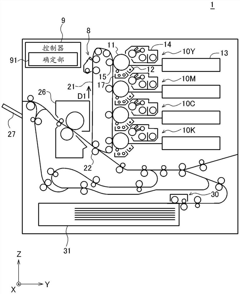
[0085] The image forming apparatus 1 is an apparatus that develops an electrostatic latent image on an image carrier to form an image. Here, an electrophotographic printing output device is exemplified as an image forming apparatus, and more specifically, a tandem full-color printing output device is exemplified. It should be stated that in figure 1 etc., use an XYZ orthogonal coordinate system to represent directions and the like.

[0086] Such as figure 1As shown, the image forming apparatus 1 includes a plurality of (specifically, four) imaging units 10 (specifically, 10Y, 10M, 10C, 10K). Specifically, the image forming apparatus 1 includes an imaging unit 10Y for yellow, an imaging unit 10M for magenta, an imaging unit 10C for cyan, and an imaging unit 10K for black. Each imaging unit 10 respectively forms an image of each color component (specifically, each component of Y (yellow), M (magenta), C (cyan), and K (black)) in the final output image by electrop...

no. 2 approach >

[0184] The second embodiment is a modified example of the first embodiment. Hereinafter, the description will focus on differences from the first embodiment.

[0185] In the first embodiment described above, the reference value V10 ( V11 ) related to whether or not to perform the patch forming operation is fixed.

[0186] In contrast, in the second embodiment, the reference value V10 is changed according to the amount of lubricant supplied to the surface of the photoreceptor 11 .

[0187] Here, to the photoreceptor 11 ( figure 1 ) is coated (supplied) with a lubricant (slip agent) that reduces the coefficient of friction of the photoreceptor 11 . The lubricant applied to the surface of the photoreceptor 11 is transferred from the photoreceptor 11 to the intermediate transfer belt 21 during the image forming operation. When the lubricant transferred from the photoreceptor 11 to the intermediate transfer belt 21 and the paper dust transferred from the paper (non-coated paper...


PUM


Abstract

The invention provides an image forming apparatus and a computer readable storage medium storing a program, which can more reliably remove aggregates from a cleaning member. An image forming apparatusincludes an image carrier (e.g., a transfer belt (21)) and a cleaning member (e.g., a cleaning blade (2)) configured to scrape residual toner on the transfer belt along with relative movement with the transfer belt. The image forming apparatus performs a maintenance operation of removing aggregates generated between the transfer belt and the cleaning blade. The maintenance operation includes a patch forming operation of forming a toner image (patch image (P50)) for removing the aggregate on the transfer belt, and a moving operation of causing the transfer belt to travel toward the cleaning blade to cause the patch image (P50) on the transfer belt to collide with the cleaning blade. The downstream edge (E1) of the patch image (P50) in the travel direction (D1) extends in a direction (C1) that is not perpendicular to the travel direction (D1).

Description

technical field [0001] The present invention relates to an image forming device and technologies associated therewith. Background technique [0002] In an image forming apparatus (specifically, an electrophotographic image forming apparatus), a toner image formed on an image carrier (such as a transfer belt) is transferred to paper (transfer material), thereby An image is formed on the paper. [0003] After such an image forming operation (transfer operation of a toner image onto paper), a part of the toner remains on the image carrier. The toner remaining on the image carrier (also referred to as residual toner) prevents new image formation, so it is scraped off by a cleaning member (cleaning blade, etc.) placed in contact with the surface of the image carrier and recovered to Toner recycling department, etc. [0004] In addition, not only residual toner but also various foreign substances are present on the image carrier after performing an image forming operation on pa...

Claims


Application Information

Patent Timeline
Patent Type & Authority Applications(China)
IPC IPC(8): G03G21/00G03G21/16
CPCG03G21/0011G03G21/007G03G21/169
Inventor 高井隆幸
Owner KONICA MINOLTA INC
Why Eureka
Try Eureka