
Interlayer fine depictiing method under reservoir configuration constraint and interlayer embedded modeling method under reservoir configuration constraint

A technology of interlayers and reservoirs, applied in the field of fine characterization of interlayers and embedded modeling, which can solve problems such as incomplete numerical simulation results, inaccuracy, and loss of interlayer information

Pending Publication Date: 2020-12-08
SHAANXI YANCHANG PETROLEUM GRP
View PDF0 Cites 2 Cited by
  • Summary
  • Abstract
  • Description
  • Claims
  • Application Information

AI Technical Summary

Problems solved by technology

[0005] Aiming at the defects of the prior art, the present invention provides a method for finely describing interlayers under the constraint of reservoir configuration, which can effectively solve the problems of lost or incomplete information on interlayers and inaccurate numerical simulation results during the coarsening process of traditional models; At the same time, according to the data determined by the fine characterization method of the interlayer, the present invention also provides an embedded modeling method of the interlayer under the constraints of the reservoir configuration

Method used


Image

  • Interlayer fine depictiing method under reservoir configuration constraint and interlayer embedded modeling method under reservoir configuration constraint
  • Interlayer fine depictiing method under reservoir configuration constraint and interlayer embedded modeling method under reservoir configuration constraint
  • Interlayer fine depictiing method under reservoir configuration constraint and interlayer embedded modeling method under reservoir configuration constraint

Examples


Embodiment 1

[0047] A method for finely characterizing interlayers under the constraint of reservoir architecture, comprising the following steps:

[0048](1) Use core facies and logging facies to identify different levels of reservoir architecture interfaces: use core facies data to identify and interpret different levels of reservoir architecture interfaces in the vertical direction of a single well, including muddy interlayers and calcareous interlayers. Interlayers, shaly interlayers, and calcareous interlayers. By establishing the corresponding relationship between core facies and logging facies, an interpretation model for the vertical logging configuration interface of a single well is established, and this interpretation model is used in uncored wells. The identification and interpretation of different levels of reservoir architecture interface is carried out; wherein, the logging response characteristics of the muddy interlayer are: the spontaneous potential SP and natural gamma ra...

Embodiment 2

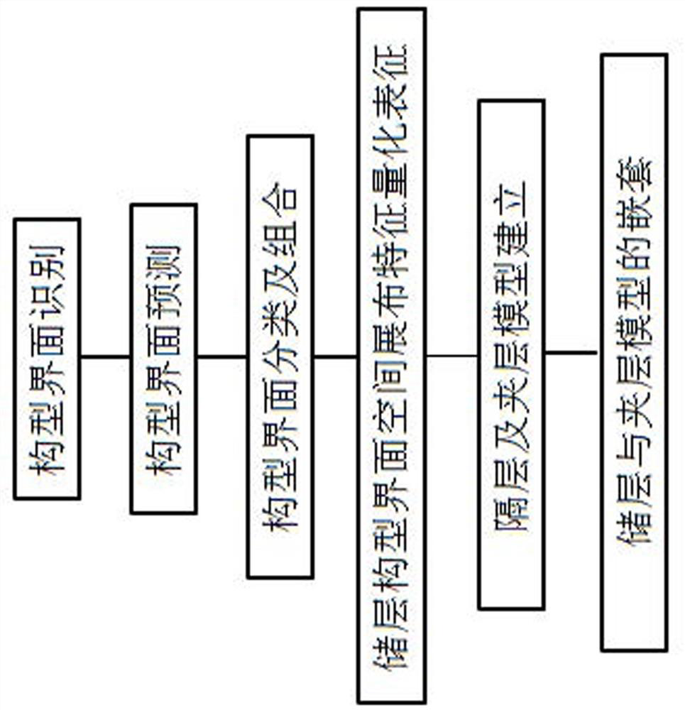
[0062] An embedded modeling method for interlayers under the constraints of reservoir architecture, the flow chart is shown in figure 1 , including the following steps:

[0063] (1) Establishment of reservoir interlayer and interlayer models:

[0064] (11) Establishment of reservoir interlayer model:

[0065] (111) Establishing the top and bottom trend surface models of the interlayer based on the corresponding depth and thickness data of the interlayer obtained in step (4) of the above embodiment 1;

[0066] (112) In the structural modeling, directly use the top and bottom trend surface models of the interlayer in step (111) to establish the structural model of the interlayer;

[0067] (113) During the facies modeling process, the interlayer facies model is established by assigning values. Both the interlayer facies model and the attribute parameter model are assigned a value of "0", and the grid system is set with one grid vertically;

[0068] (12) Establishment of reserv...

Embodiment 3

[0076] In this embodiment, the S block in the Fuxian area of ​​Yanchang Oilfield in the south of the Ordos Basin is taken as an example to specifically analyze and illustrate the present invention. The study area is located in the south of the Ordos Basin, and the internal structure of the block is simple, a west-dipping monocline with no fault development; the main target layer in the study area is the Chang 8 oil layer group of the Yanchang Formation, and the main sedimentary backgrounds are delta front and prodelta Sub-facies deposits, mainly developed three types of microfacies: underwater distributary channel, inter-aqueous distributary channel and prodelta mud; the main sublayer is 8 2 The lithology of the small layer is mainly fine sandstone, followed by silt fine sandstone, the particles are mostly in the shape of edges and subrounds, the debris is severely weathered, the sorting and rounding are moderate, point-line contact, and the average porosity is 9.76%; The aver...


PUM

PropertyMeasurementUnit
Thicknessaaaaaaaaaa

Abstract

The invention discloses an interlayer fine depicting method under reservoir configuration constraint. The interlayer fine depicting method comprises the following steps: (1) identifying reservoir configuration interfaces at different levels by utilizing a core facies and a log facies; (2) predicting reservoir configuration interfaces at different levels by utilizing a geological deposition mode, horizontal well drilling, oil-water well production dynamics and test data; (3) classifying and combining reservoir configuration interfaces at different levels; (4) carrying out quantitative characterization on spatial distribution characteristics of the reservoir configuration interfaces at different levels, wherein the reservoir configuration interfaces at different levels comprise corresponding4-level and 5-level reservoir configuration interfaces under different sedimentary microfacies. In addition, according to the data determined by the interlayer fine depicting method, the invention further discloses an interlayer embedded modeling method under the reservoir configuration constraint, which can achieve complete reservation of interlayer information after coarsening of a reservoir model, and has important guiding significance for later-period oil reservoir numerical simulation research on remaining oil distribution characteristics.

Description

technical field [0001] The invention belongs to the technical field of petroleum and natural gas exploration and development, and in particular relates to a method for finely depicting interlayers and embedded modeling under the constraint of reservoir configuration. Background technique [0002] During oilfield development, interlayers have an important influence on oil and gas seepage, which controls the seepage of fluid in the reservoir and the distribution of remaining oil, which has become the focus of fine geological research; 3D reservoir geological modeling is a current technology Mature 3D visualization reservoir characterization technology, which can display the development law of the reservoir interlayer model in 3D, is useful for guiding the analysis of the effect of injection-production well groups in the fine development of water injection, horizontal well geosteering adjustment while drilling, and local remaining oil Issues such as distribution research, low d...

Claims


Application Information

Patent Timeline
IPC IPC(8): G06F30/20G06T17/05G01V99/00E21B49/00G06F111/04G06F111/10
CPCG06F30/20G06T17/05E21B49/00G06F2111/04G06F2111/10G01V20/00Y02A10/40
Inventor 梁卫卫赵习森刘滨党海龙蔺建武张亮杨江石彬王振宇张天龙曹玉珊张佳琪李留杰凃兴平李东
Owner SHAANXI YANCHANG PETROLEUM GRP
Learn More