Mobile terminal and antenna device

A mobile terminal and antenna device technology, applied in the field of communication, can solve the problems of weakening antenna data transmission capability and low radiation efficiency

Active Publication Date: 2020-12-08
QINGDAO HISENSE MOBILE COMM TECH CO LTD
View PDF6 Cites 0 Cited by
  • Summary
  • Abstract
  • Description
  • Claims
  • Application Information

AI Technical Summary

Problems solved by technology

[0003] In order to improve the channel capacity and data throughput of the mobile terminal, the 4G LTE (Long Term Evolution, long-term evolution network) standard tablet will adopt multi-antenna technology, that is, multiple antennas are used at the transmitting end and the receiving end to transmit and receive signals. However, in Under the current development trend of mobile terminals with intelligence, ultra-thin, large screen and integration of multiple communication systems, although the volume of mobile terminals is getting smaller and smaller, it needs to accommodate more hardware. More and more antennas will be integrated inside, which will weaken the data transmission capability of the antenna. This is because, as the integration density of the antenna increases, it will lead to the occurrence of mutual coupling between multiple antennas, resulting in low radiation efficiency.

Method used


Image

  • Mobile terminal and antenna device
  • Mobile terminal and antenna device

Examples


Embodiment Construction

[0025] In order to make the above objects, features and advantages of the present invention more comprehensible, the present invention will be further described in detail below in conjunction with the accompanying drawings and specific embodiments.

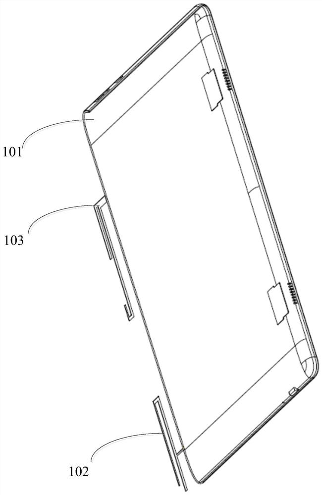
[0026] refer to figure 1 , showing a structural diagram of a mobile terminal of the present invention, which may specifically include:

[0027] A housing 101, a main antenna 102 and a diversity antenna 103 connected to the housing 101;

[0028] The main antenna 102 includes a short axis of the main antenna and a long axis of the main antenna, the short axis of the main antenna is connected to the end of the long side of the housing 101, and the long axis of the main antenna is parallel to the long side of the housing 101 ;

[0029] The diversity antenna 103 includes a short axis of the diversity antenna and a long axis of the diversity antenna, the short axis of the diversity antenna is connected to the midpoint of the long side...


PUM


Abstract

The embodiment of the invention provides a mobile terminal. The mobile terminal comprises a shell, and a main antenna and a diversity antenna which are connected with the shell, the main antenna comprises a main antenna short shaft and a main antenna long shaft, the main antenna short shaft is connected with the tail end of the long side of the shell, and the main antenna long shaft is parallel tothe long side of the shell; the diversity antenna comprises a diversity antenna short shaft and a diversity antenna long shaft, the diversity antenna short shaft is connected with the midpoint of thelong side of the shell, and the diversity antenna long shaft is parallel to the long side of the shell; longitudinal currents excited by the diversity antenna in the long side direction and transverse currents excited by the main antenna in the short side direction are distributed on the shell. The longitudinal current at the midpoint of the long side of the shell is maximum, and the transverse current at the tail end of the short side of the shell is minimum. Through the embodiment of the invention, the isolation degree between the main antenna and the diversity antenna is effectively improved, so that the mutual coupling influence between the main antenna and the diversity antenna is effectively reduced on the premise of not increasing the physical distance between the main antenna andthe diversity antenna, and the radiation efficiency of the antenna is further improved.

Description

technical field [0001] The present invention relates to the technical field of communication, in particular to a mobile terminal and an antenna device. Background technique [0002] With the development of smart technology, mobile devices such as mobile phones and smart wearable devices have become the most important communication tools for people. In most cases, the mobile terminal needs to transmit and receive wireless signals through an antenna, and the data transmission capability of the antenna directly affects the communication quality of the mobile terminal. [0003] In order to improve the channel capacity and data throughput of the mobile terminal, the 4G LTE (Long Term Evolution, long-term evolution network) standard tablet will adopt multi-antenna technology, that is, multiple antennas are used at the transmitting end and the receiving end to transmit and receive signals. However, in Under the current development trend of mobile terminals with intelligence, ultra...

Claims


Application Information

Patent Timeline
Patent Type & Authority Applications(China)
IPC IPC(8): H01Q1/36H01Q1/50H01Q1/24H01Q1/42
CPCH01Q1/36H01Q1/50H01Q1/241H01Q1/42
Inventor 张林光
Owner QINGDAO HISENSE MOBILE COMM TECH CO LTD
Why Eureka
Try Eureka