Automatic feeding tremella picking machine
An automatic feeding and picking machine technology, applied in horticulture, agriculture, plant cultivation and other directions, can solve the problems of large labor force, consumption, easy-to-break Tremella structure, etc., and achieve the effect of improving work efficiency and reducing losses
- Summary
- Abstract
- Description
- Claims
- Application Information
AI Technical Summary
Problems solved by technology
Method used
Image
Examples
Embodiment 1
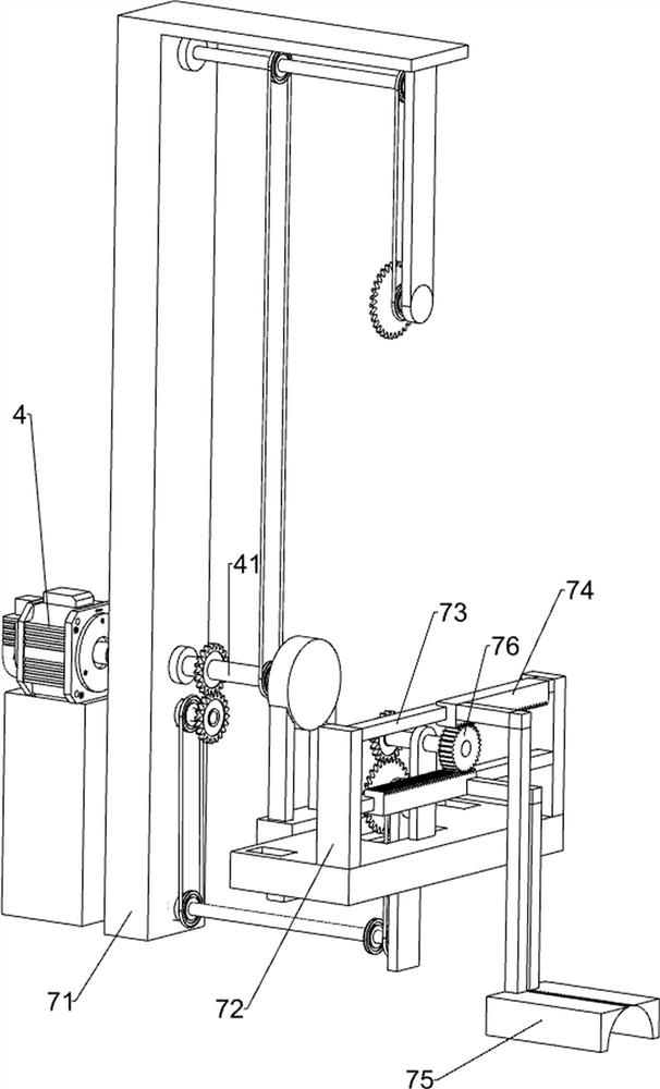
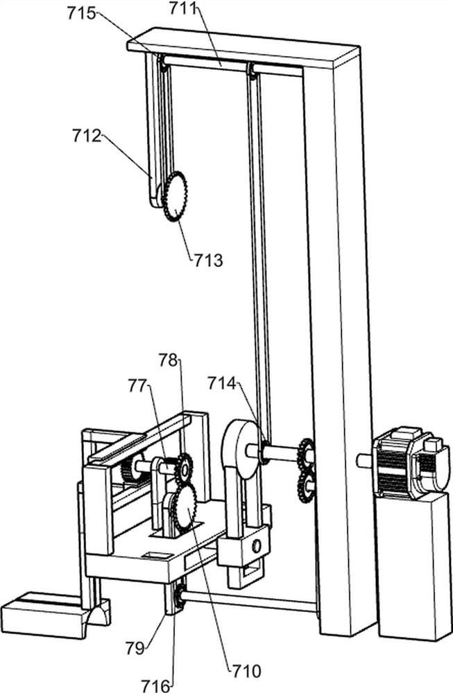
[0071] A tremella picking machine with automatic feeding, such as Figure 1-2 Shown, include floor 1, first support 2, desktop 3, motor 4, first rotating shaft 41, second rotating shaft 42, the 3rd rotating shaft 43, first gear 44, first pulley 45, first transmission belt 46, The transportation mechanism 5, the lifting mechanism 6 and the clamping mechanism 7, the first support 2 is connected to the left, the front, the rear, the left and the right sides of the floor 1, the desktop 3 is connected between the tops of the first supports 2, and the middle part of the right side of the desktop 3 has a circular groove , the motor 4 is connected in the middle on the left side of the top of the desktop 3, the lifting mechanism 6 is connected on the top of the desktop 3, the clamping mechanism 7 is connected between the top of the desktop 3 and the lifting mechanism 6, the transportation mechanism 5 is connected on the right side of the floor 1, and the output of the motor 4 The first...
Embodiment 2
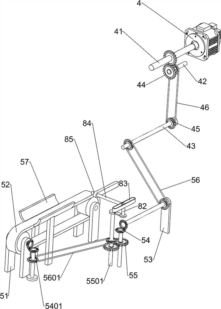
[0074] On the basis of Example 1, such as Figure 2-3 As shown, the transportation mechanism 5 includes a second bracket 51, a transportation assembly 52, a third bracket 53, a first steering gear set 54, a second steering gear set 5401, a third gear assembly 55, a supporting shaft 5501, a first transmission assembly 56. The second transmission assembly 5601 and the baffle plate 57. The right part of the floor 1 is connected with the second support 51 on the front, rear, left, and right sides. The transport assembly 52 is connected in rotation between the second supports 51. The front and rear sides of the right part of the floor 1 are connected with The baffle plate 57, the transport assembly 52 is located between the baffle plates 57, the right rear side of the floor 1 is connected with a rotary rod in a rotational manner, the second steering gear set 5401 is connected between the top of the rotary rod and the right rear part of the transport assembly 52, the floor 1. The re...
Embodiment 3
[0079] On the basis of Example 2, such as figure 1 , figure 2 , Figure 4 and Figure 5 As shown, the clamping mechanism 7 includes a fourth bracket 71, a fifth bracket 72, a third slide rail 73, a rack 74, a clip 75, a transmission gear 76, a fifth rotating shaft 77, a second gear 78, and a sixth bracket 79 , the first large internal diameter gear 710, the sixth rotating shaft 711, the connecting plate 712, the second large internal diameter gear 713, the fifth transmission belt set 714 and the third transmission belt set 715, the middle of the top left side of the desktop 3 is connected with the fourth support 71 , the fourth bracket 71 is located on the right side of the motor 4, the bottom of the fourth bracket 71 is rotationally connected with the first rotating shaft 41, the second rotating shaft 42 and the third rotating shaft 43, and the top, front and rear sides of the right side of the bearing plate 62 are connected with the fifth bracket 72. A third slide rail 7...
PUM
 Abstract
Description
Claims
Application Information
 - R&D
- Intellectual Property
- Life Sciences
- Materials
- Tech Scout
- Unparalleled Data Quality
- Higher Quality Content
- 60% Fewer Hallucinations
Browse by: Latest US Patents, China's latest patents, Technical Efficacy Thesaurus, Application Domain, Technology Topic, Popular Technical Reports.
© 2025 PatSnap. All rights reserved.Legal|Privacy policy|Modern Slavery Act Transparency Statement|Sitemap|About US| Contact US: help@patsnap.com


