
Punching mechanism for automobile reinforcing plate machining

A technology for reinforcing plates and automobiles, which is applied to metal processing equipment, mechanical equipment, manufacturing tools, etc., can solve the problems of reducing the processing efficiency of reinforcing plates, increasing the processing cost of reinforcing plates, and uneven surface of the reinforcing plates, and increasing the contact area, reduce leakage, and improve the effect of sealing

Active Publication Date: 2020-12-11
CHONGQING JIA FENG AUTO PARTS
View PDF10 Cites 0 Cited by
  • Summary
  • Abstract
  • Description
  • Claims
  • Application Information

AI Technical Summary

Problems solved by technology

[0003] For example, the reinforcement plate installed by bolts needs to be punched on the reinforcement plate. After punching, the bolts can pass through and be locked on various parts of the car. Since the thickness of the reinforcement plate is not large, the punch can quickly punch the punching position. It will cause the plate around the hole to bend downwards, making the surface of the reinforcement plate uneven, which will lead to the need for secondary reinforcement of the reinforcement plate, that is, leveling the punching position of the reinforcement plate, which will inevitably increase the processing cost and processing time of the reinforcement plate , reducing the processing efficiency of the reinforced plate

Method used


Image

  • Punching mechanism for automobile reinforcing plate machining
  • Punching mechanism for automobile reinforcing plate machining
  • Punching mechanism for automobile reinforcing plate machining

Examples


Embodiment

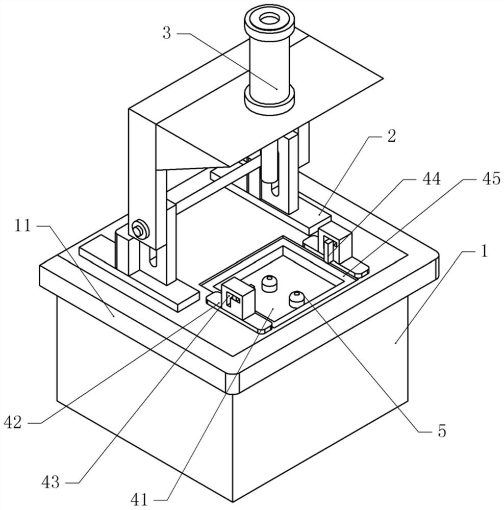
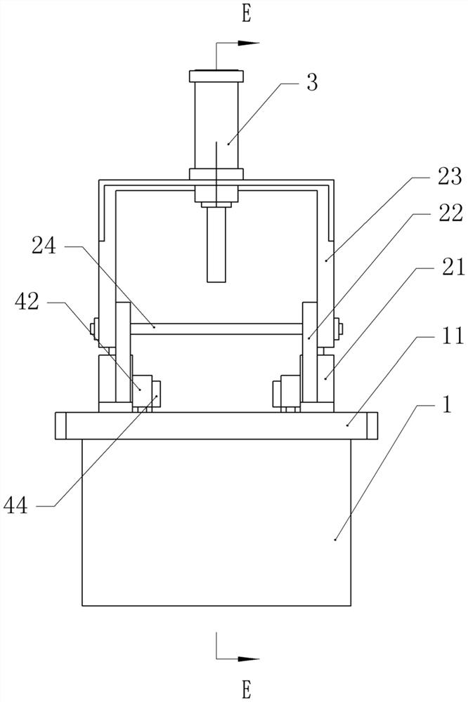
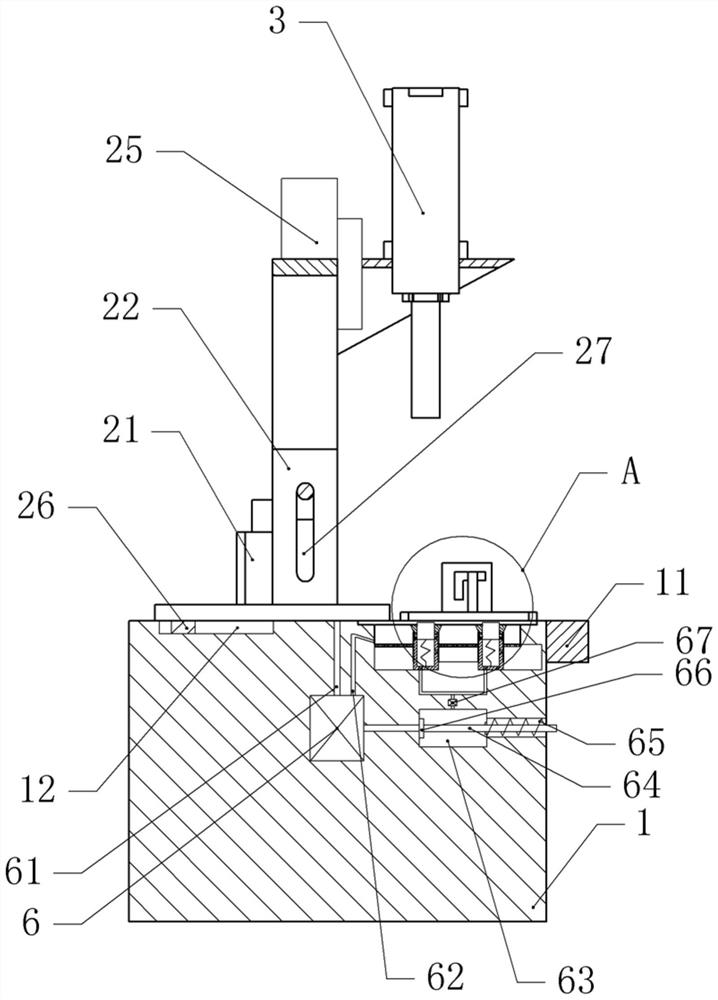
[0034] Basic as attached figure 1 , attached figure 2 And attached image 3 As shown, a punching mechanism for processing automobile reinforcement plates includes a punching table 1 and a bracket 2 installed on the punching table 1 . The punching table 1 is welded with a boss 11, and the boss 11 stretches out from the punching table 1, and the boss 11 prevents the operator from getting too close to the punching table 1.

[0035] The support 2 includes a fixed frame 23 and movable seats 22 positioned at both sides of the fixed frame 23. The bolts on the fixed frame 23 are fixed with the stamping head 3, the bolts on the fixed frame 23 are fixed with the connecting shaft 24, and the movable seats 22 are provided with guide grooves 27. , the connecting shaft 24 is vertically slidably connected with the guide groove 27 . Both sides of the fixed frame 23 are provided with a cylinder 21 bolted on the movable seat 22, and the output shaft of the cylinder 21 is fixedly connected w...


PUM


Abstract

The invention relates to the technical field of punching, and discloses a punching mechanism for automobile reinforcing plate machining. The mechanism comprises a punching table, and the punching table is provided with a punching head. The mechanism is characterized in that the punching table is provided with a punching groove located below the punching head; the upper part of the punching grooveis provided with a positioning groove; the two sides of the positioning groove are respectively provided with a fixing part; each of the fixing parts comprises a fixing base and a sliding groove; fixing blocks slidably connected with the sliding grooves is arranged inside the sliding grooves; a plurality of supporting shafts are arranged in the punching groove; each of the supporting shafts comprises a hollow outer shaft; a supporting table is arranged on the upper portion of each of the outer shafts; bulges vertical to the outer shafts are fixed to the lower portions of the supporting tables;inner shafts are vertically connected with the interiors of the supporting tables in a sliding mode; elastic parts fixedly connected with the outer shafts are arranged at the bottoms of the inner shafts; and pushing blocks for pushing the bulges are arranged on the inner shafts. The punching mechanism for automobile reinforcing plate machining is simple in structure, and plates around holes can be prevented from deforming greatly during punching, so that the machining efficiency of reinforcing plates is improved.

Description

technical field [0001] The invention relates to the technical field of punching, and specifically discloses a punching mechanism for processing automobile reinforcement plates. Background technique [0002] Reinforcement plates for automobiles are used to strengthen various parts of automobiles to improve the stability and strength of various parts of automobiles. The installation of automobile reinforcement plates includes welding and bolt fixing. [0003] For example, the reinforcement plate installed by bolts needs to be punched on the reinforcement plate. After punching, the bolts can pass through and be locked on various parts of the car. Since the thickness of the reinforcement plate is not large, the punch can quickly punch the punching position. It will cause the plate around the hole to bend downwards, making the surface of the reinforcement plate uneven, which will lead to the need for secondary reinforcement of the reinforcement plate, that is, leveling the punchi...

Claims


Application Information

Patent Timeline
Patent Type & Authority Applications(China)
IPC IPC(8): B21D28/26B21D28/04B21D45/02B21D53/88F16J15/16
CPCB21D28/26B21D28/04B21D45/003B21D45/02B21D53/88F16J15/16
Inventor 胡承前黄骏杰
Owner CHONGQING JIA FENG AUTO PARTS
Learn More