
Numerical control stone cutting machine, cutting tool bit and control method of cutting tool bit

A cutting head, stone cutting machine technology, applied in electrical program control, program control in sequence/logic controllers, manufacturing tools, etc., can solve waste, does not have the structure and function of moving stone unit panels at will, and is easy to bruise Stone unit board and other problems, to achieve the effect of reducing waste, simple structure and simple control method

Active Publication Date: 2020-12-11
FUJIAN JINJIANG SHENGDA MACHINERY
View PDF9 Cites 1 Cited by
  • Summary
  • Abstract
  • Description
  • Claims
  • Application Information

AI Technical Summary

Problems solved by technology

The general structure of the existing bridge stone cutter is: including base, workbench, side frame, beam, vertical travel mechanism, horizontal travel mechanism, lifting and cutting mechanism, cutting linkage seat, cutting device, C-axis rotary drive mechanism, A Shaft rotation drive mechanism, and PC industrial control operation box; but the existing bridge-type stone cutter does not have the structure and function of moving the stone unit plate on the workbench at will. The stone unit board on the cutting line is easy to damage the stone unit board hindering the cutting line, resulting in unnecessary waste, which needs further improvement

Method used


Image

  • Numerical control stone cutting machine, cutting tool bit and control method of cutting tool bit
  • Numerical control stone cutting machine, cutting tool bit and control method of cutting tool bit
  • Numerical control stone cutting machine, cutting tool bit and control method of cutting tool bit

Examples


Embodiment Construction

[0038] The present invention will be further described below through specific embodiments.

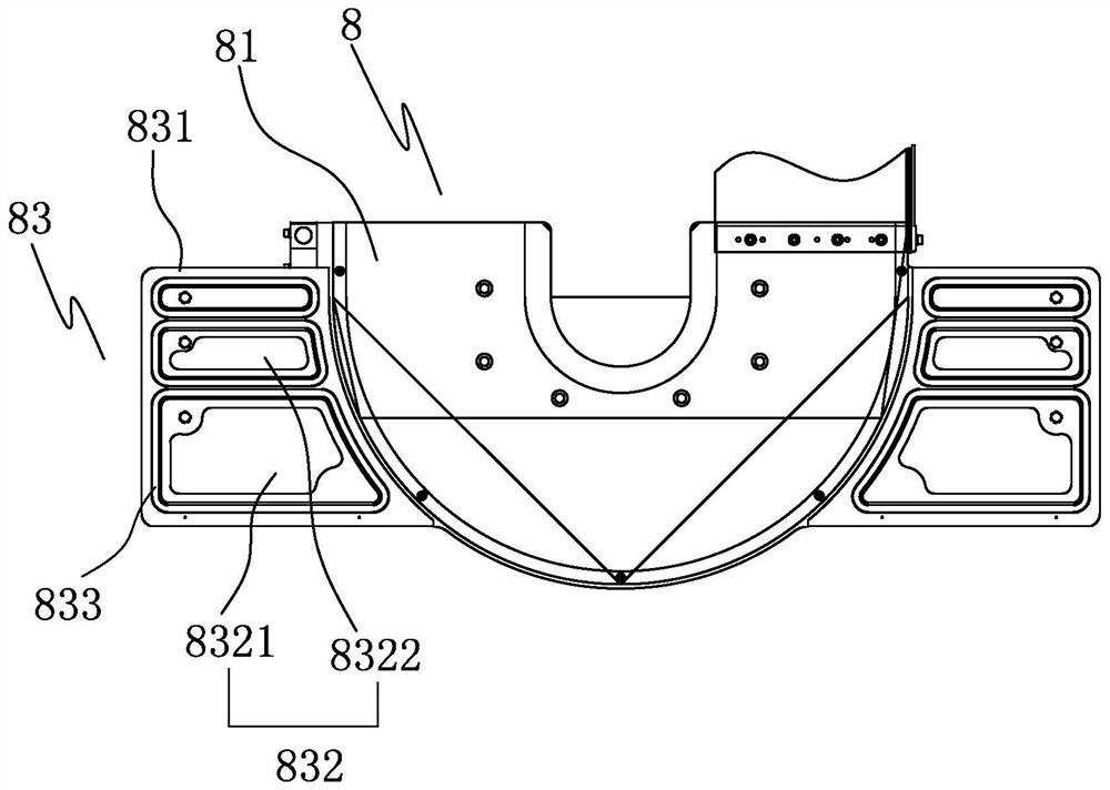
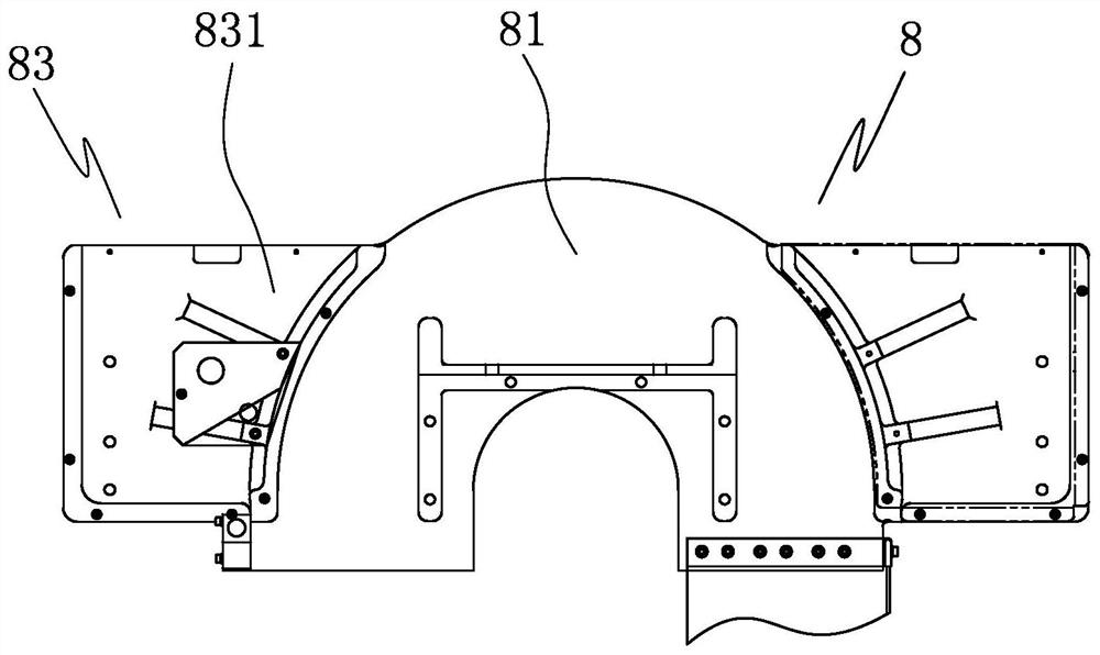
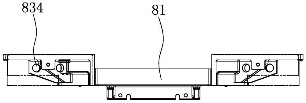
[0039] refer to Figure 1 to Figure 15 As shown, a five-axis CNC stone cutter includes a frame 1, a workbench 2, a cutter head mounting frame 3, a cutting cutter head 8 and a driving device.

[0040] The frame 1 includes two bases 11 oppositely arranged and a beam 12 arranged between the two bases 11 which can move back and forth.

[0041] The workbench 2 is arranged between the two bases 11 for placing stone materials.

[0042] The cutter head installation frame 3 is arranged on the crossbeam 12, is used for installing the cutting cutter head 8, comprises the bottom frame 31 that can move left and right to be arranged on the crossbeam 12, can move up and down and be arranged on the lifting frame 32 that is arranged on the bottom frame 31 and be arranged on the lifting frame 31. A rotating frame 33 that can rotate around a vertical axis on the frame 32.

[0043] The drive device is us...


PUM


Abstract

The invention discloses a numerical control stone cutting machine, a cutting tool bit and a control method of the cutting tool bit. The stone cutting machine comprises a rack, a tool bit mounting frame arranged on the rack and a driving device for driving the tool bit mounting frame to act; the cutting tool bit comprises a cutting saw blade, a tool cover arranged on the tool bit mounting frame andused for mounting the cutting saw blade, a suction cup arranged on the tool cover and a pneumatic control device connected with the suction cup to control the suction cup to work; the suction cup comprises a plurality of adsorption ports formed at intervals and rubber rings arranged on the peripheries of the adsorption ports in a surrounding mode; the pneumatic control device is correspondingly connected with the plurality of adsorption ports so as to correspondingly control the plurality of adsorption ports to work; the pneumatic control device comprises an air source, a main air path connected with the air source, a plurality of negative pressure generation assemblies which are connected with the main air path and are in one-to-one correspondence with a plurality of adsorption ports, anegative pressure air path connected between the negative pressure generation assemblies and the adsorption ports, a negative pressure meter arranged on the negative pressure air path, and a controller connected with the negative pressure meter; and the controller receives and processes data fed back by the negative pressure meter to judge whether the suction cup adsorbs the stone or not.

Description

technical field [0001] The invention belongs to the field of stone cutters, and in particular relates to a numerically controlled stone cutter, a cutting head and a control method thereof. Background technique [0002] Stone cutters are widely used in construction, decoration and other industries. They are suitable for cutting all kinds of stone, building materials, granite, marble, etc. Bridge stone cutters are the most common type of stone cutters. At present, before using a stone cutter to cut large stone slabs, it is usually necessary to automatically take pictures of the stone through the camera above the machine and transmit them to the computer. Marking; the computer will automatically arrange the best layout scheme and cutting scheme on the image according to the arrangement and combination of patterns on the large stone slab and the elimination of defective parts, so as to ensure the high utilization rate of the entire stone. The general structure of the existing b...

Claims


Application Information

Patent Timeline
IPC IPC(8): B28D1/04B28D7/00B28D7/04G05B19/05
CPCB28D1/044B28D7/00B28D7/005B28D7/04G05B19/05Y02P70/10
Inventor 苏永定许俊枫黄广华王德怀孔庆森张永灿苏华文张海李汉寿简奇仁王杰雄蔡毅鹏
Owner FUJIAN JINJIANG SHENGDA MACHINERY
Learn More