Intelligent B-pillar trim panel assembly of automobile and identity recognition method
A technology of identity recognition and decorative panels, which is applied to vehicle parts, biometric identification, character and pattern recognition, etc. It can solve the problems of affecting the shooting effect, affecting the appearance, and destroying the decoration effect of the B-pillar decorative panels, so as to improve the aesthetics, High safety effect
- Summary
- Abstract
- Description
- Claims
- Application Information
AI Technical Summary
Problems solved by technology
Method used
Image
Examples
Embodiment 1
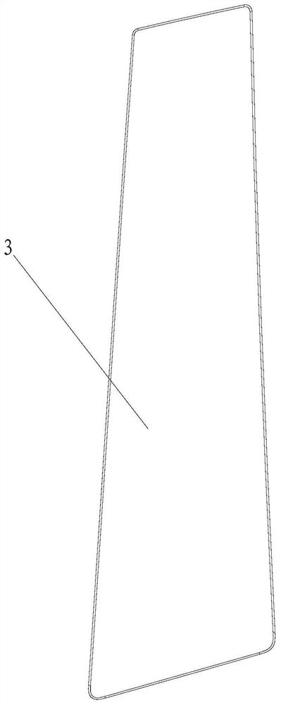
[0057] refer to Figure 1-Figure 6 , a smart B-pillar trim assembly for an automobile, comprising an infrared identification module 1, a base 2, a trim body 3 for connecting with a B-pillar and having high infrared transmittance, and a trim body 3 that matches and Covering layer 4 with high infrared transmittance;
[0058] The concealment layer 4 and the base 2 are sequentially installed between the trim body 3 and the B-pillar, so that the concealment layer 4 covers the base 2;
[0059] The infrared identification module 1 is installed on one side of the base 2, and the infrared identification module 1 is electrically connected with the BCM6 of the automobile.
[0060] Preferably, the concealment layer 4 and the base 2 are sequentially installed on the side of the trim body 3 facing the B-pillar;
[0061] Wherein, the base 2 is a metal plate or a plastic plate, and the side of the base 2 facing the trim body 3 is provided with a plurality of connecting columns 5 , and the c...
Embodiment 2
[0063] refer to Figure 6 , the infrared recognition module 1 includes an image acquisition unit 11, a supplementary light unit 12, a control module 13 and a power protection module 15; One side; control module 13, image acquisition unit 11 and power supply protection module 15 are electrically connected with vehicle-mounted power supply by power supply protection module 15 respectively, so that circuit is protected; and the control module 13 is electrically connected to the BCM6 through the connector 16. Preferably, the control module 13 is an MCU. Wherein, the MCU also includes a light control module 122 , a power output module 151 , and a communication module 14 . Preferably, the manufacturer of the MCU is NXP, and the model is I.MX8 series with communication interface and power output.
[0064] refer to figure 1 and Figure 6 , the image acquisition unit 11 includes an infrared optical lens 111 and an image processing module 112 ; the infrared optical lens 111 is elec...
Embodiment 3
[0072] The difference between this embodiment and the second embodiment is that another structure of the optical film layer is defined.
[0073] refer to Figure 7 The optical film layer 42 is attached to the side of the decorative panel body 3 facing the B-pillar sheet metal, and is only attached to the field angle area of the image acquisition part 11 and the light transmission area of the supplementary light part 12, while in the image acquisition part Ink is applied to the field angle area of 11 and the area outside the light transmission area of the supplementary light part 12 . The color chromaticity difference between the ink and the masking layer is ΔE≤1.5, which ensures the consistency of appearance and color.
PUM
 Abstract
Description
Claims
Application Information
 - R&D
- Intellectual Property
- Life Sciences
- Materials
- Tech Scout
- Unparalleled Data Quality
- Higher Quality Content
- 60% Fewer Hallucinations
Browse by: Latest US Patents, China's latest patents, Technical Efficacy Thesaurus, Application Domain, Technology Topic, Popular Technical Reports.
© 2025 PatSnap. All rights reserved.Legal|Privacy policy|Modern Slavery Act Transparency Statement|Sitemap|About US| Contact US: help@patsnap.com


