Carriage plate structure provided with protective structure and used for conveying pipes and reinforcing steel bars

A protective structure and compartment panel technology, which is applied in the field of transport vehicles, can solve the problems of driver safety impact and poor protection effect, and achieve the effect of convenient rain protection and avoiding inertial high-speed movement

Inactive Publication Date: 2020-12-11
吴玮
View PDF0 Cites 1 Cited by
  • Summary
  • Abstract
  • Description
  • Claims
  • Application Information

AI Technical Summary

Problems solved by technology

[0004] The object of the present invention is to provide a kind of pipe material that is provided with protective structure, steel bar conveyance carriage plate structure, to solve the above-mentioned background technology when a large amount of steel pipes or steel bar materials are placed in the carriage, the overall weight can be as high as tens of tons, and Most of the existing backboards are simple metal plate structures. When the vehicle is running, once it encounters an emergency brake, it is very easy to move forward instantly due to the overall inertia of the steel pipe and steel reinforcement material, directly penetrating the backboard and Breaking through the cab has a great impact on the safety of the driver, and the existing technology structure only increases the thickness of the back plate or uses a steel frame in the compartment, but the actual protection effect is poor

Method used


Image

  • Carriage plate structure provided with protective structure and used for conveying pipes and reinforcing steel bars
  • Carriage plate structure provided with protective structure and used for conveying pipes and reinforcing steel bars
  • Carriage plate structure provided with protective structure and used for conveying pipes and reinforcing steel bars

Examples


Embodiment Construction

[0023] The following will clearly and completely describe the technical solutions in the embodiments of the present invention with reference to the accompanying drawings in the embodiments of the present invention. Obviously, the described embodiments are only some, not all, embodiments of the present invention. Based on the embodiments of the present invention, all other embodiments obtained by persons of ordinary skill in the art without making creative efforts belong to the protection scope of the present invention.

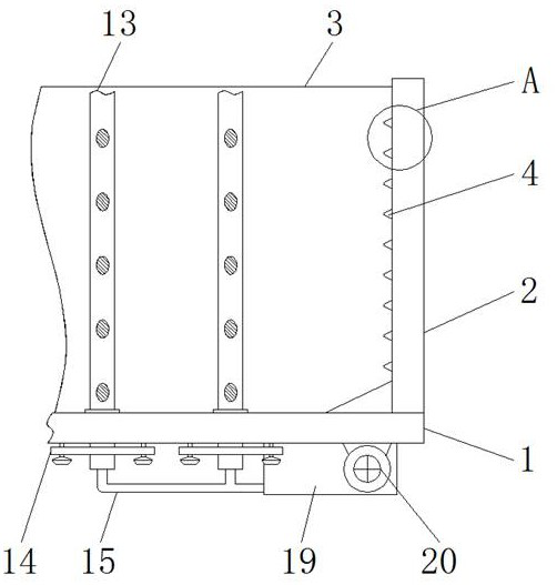
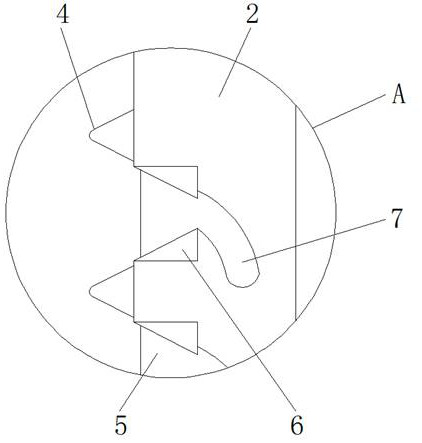
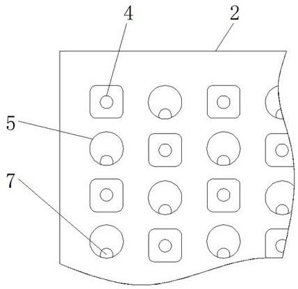
[0024] see Figure 1-6 , the present invention provides a technical solution: a pipe provided with a protective structure, and a car plate structure for steel bar transportation, including a car floor 1, a back plate 2, a side plate 3, a protective protrusion 4, a buffer hole 5, and a buffer layer 6 , buffer cavity 7, fixed rod 8, pressure rod 9, splicing rod 10, pressure groove 11, pressure bar 12, limit rod 13, mounting plate 14, air pipe 15, cavity 16, air ...


PUM


Abstract

The invention discloses a carriage plate structure provided with a protective structure and used for conveying pipes and reinforcing steel bars. The carriage plate structure comprises a carriage bottom plate, a back plate and side plates, the back plate and the side plates are installed on the upper end face of the carriage bottom plate, the middle sections of a pressing rod and fixing rods are each of an upwards-protruding arc-shaped structure, a pressing groove is formed in the lower end face of the pressing rod, a pressing strip matched with the pressing groove is arranged below the pressing groove and fixed to the upper end face of a fixing rod, and the lower end faces of the fixing rods are connected with the top ends of limiting rods through bolts. According to the carriage plate structure provided with the protective structure and used for conveying the pipes and the reinforcing steel bars, the inner surface structure of the back plate is redesigned, structures at the ends of the steel pipes or the reinforcing steel bars can be effectively limited, meanwhile, the structural design of the multiple limiting rods is matched, the moving resistance of the reinforcing steel bars or the steel pipes in a carriage can be increased through inflation operation, inertia high-speed movement of the reinforcing steel bars and the pipes is effectively avoided, and the protection effectis very outstanding.

Description

technical field [0001] The invention relates to the technical field of transport vehicles, in particular to a pipe and steel bar transport carriage plate structure provided with a protective structure. Background technique [0002] For long-distance transport vehicle equipment, the part used to accommodate and place materials is mainly the compartment structure at the back. The compartment structure consists of a horizontally distributed compartment floor, a compartment back panel located on the back of the cab, and vertically distributed compartment side panels located on both sides of the compartment floor. Composition, the mutual cooperation of the three, combined with the door at the end of the carriage to store and protect the conveyed objects, but the existing similar carriage plate structure has the following problems when conveying steel pipes and steel bars: [0003] When a large number of steel pipes or steel bars are placed in the car, the overall weight can be as...

Claims


Application Information

Patent Timeline
Patent Type & Authority Applications(China)
IPC IPC(8): B62D33/00B60P7/16
CPCB60P7/16B62D33/00
Inventor 吴玮
Owner 吴玮
Why Eureka
Try Eureka