A cable winding device

A technology for cables and equipment, applied in the field of cable winding equipment, can solve the problems of inconvenient removal of cables and inability to cut them in time, and achieve the effects of improving efficiency, improving quality and fast cutting

Active Publication Date: 2022-06-21
山东九州电力电线厂
View PDF15 Cites 0 Cited by
  • Summary
  • Abstract
  • Description
  • Claims
  • Application Information

AI Technical Summary

Problems solved by technology

[0006] In order to overcome the shortcomings that people use the existing equipment to rewind the cable, the cable cannot be cut in time after the cable is rewound, and it is inconvenient to take out the reeled cable. The technical problem is to provide a cable winding device that can be cut in time after the cable is rolled up, and that is more convenient when the rolled cable is taken out.

Method used


Image

  • A cable winding device
  • A cable winding device
  • A cable winding device

Examples


Embodiment 1

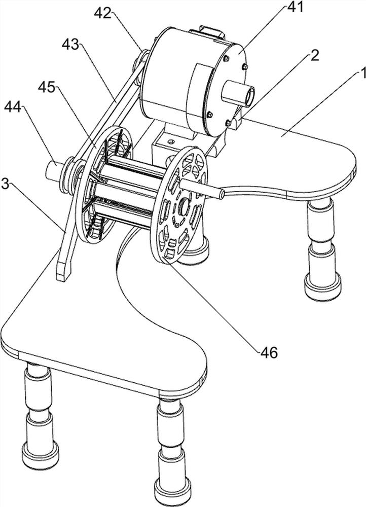
[0023] A cable winding device, such as Figure 1 to Figure 3 As shown, it includes a stand 1, a support 2, a mounting base 3, a winding mechanism 4 and a moving mechanism 5. The left rear side of the top of the stand 1 is connected with the stand 2, and the middle position of the top of the stand 1 is connected with a mounting A winding mechanism 4 is connected between the base 3 , the top of the support 2 and the upper part of the mounting base 3 , and a moving mechanism 5 is connected between the left side of the winding mechanism 4 and the front side of the top of the stand 1 .

[0024] The winding mechanism 4 includes a deceleration motor 41, a first pulley 42, a first flat belt 43, a rotating shaft 44, a winding wheel 45 and a fixed disc 46. The top of the support 2 is connected with a deceleration motor 41, and the upper part of the mounting seat 3 is rotatable. A rotating shaft 44 is connected, the output shaft of the deceleration motor 41 and the left side of the rotat...

Embodiment 2

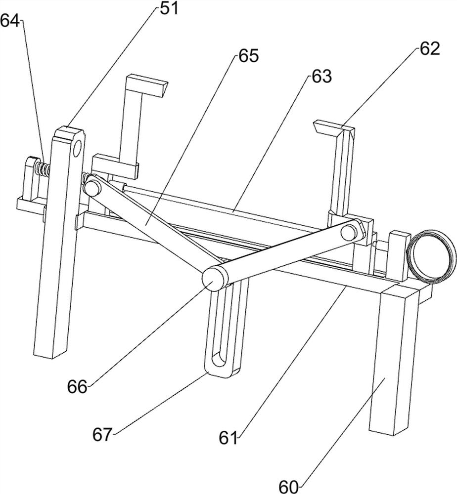
[0028] On the basis of Example 1, as Figure 4 As shown, it also includes a shearing mechanism 6, and the shearing mechanism 6 includes a fixed block 60, a sliding rod 61, an L-shaped blade 62, a pulling wire 63, a first spring 64, a connecting rod 65, a round rod 66 and a connecting block 67, A fixing block 60 is connected to the front right side of the top of the stand 1, a sliding rod 61 is connected between the upper part of the fixing block 60 and the rear side of the middle part of the fixing base 51, and L-shaped blades are slidably connected to the left and right sides of the top of the sliding rod 61. 62, the front sides of the lower parts of the two L-shaped blades 62 are hingedly connected with a connecting rod 65, the middle position of the bottom of the sliding rod 61 is connected with a connecting block 67, and the inner side of the connecting block 67 is slidably connected with a round rod 66, the round rod 66 The front side of the sliding rod 61 is hingedly con...

Embodiment 3

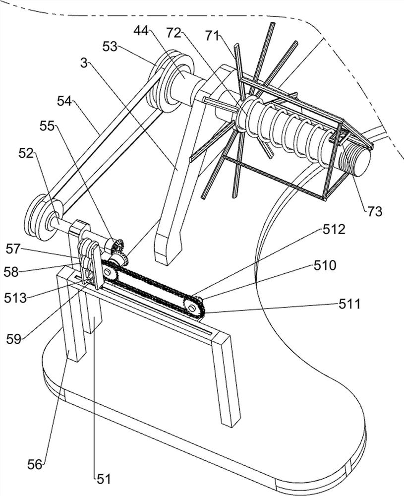
[0031] On the basis of Example 2, as image 3 and Figure 5 As shown, it also includes a push-pull mechanism 7, the push-pull mechanism 7 includes a push-pull frame 71, a second spring 72 and a handle 73, the rotating shaft 44 is slidably connected with the push-pull frame 71, and the rotating shaft 44 is sleeved with a second spring 72, The left and right ends of the second spring 72 are respectively connected with the push-pull frame 71 and the reel 45 .

[0032] When people finish winding and cutting the cable, turn the fixing plate 46 and take it out, then pull the handle 73 to slide to the right, and the second spring 72 shrinks accordingly, under the pushing action of the push-pull frame 71, the cable can be pulled out. Take it out from the reel 45, when the cable is taken out, release the handle 73, under the action of the elastic force of the second spring 72, the push-pull frame 71 and the handle 73 can be driven to reset, so that people can quickly wind up the cable...


PUM


Abstract

The invention relates to a winding device, in particular to a cable winding device. The technical problem to be solved by the present invention is to provide a cable winding device that can cut off the cable in time after winding and take out the rolled cable more conveniently. In order to solve the above technical problems, the present invention provides such a cable winding device, comprising: a support, which is connected to one side of the stand; an installation seat, which is connected to the side of the stand close to the support; The winding mechanism is connected between the support and the installation seat; the moving mechanism is connected between one side of the winding mechanism and the other side of the stand. The beneficial effects of the present invention are: through the action of the winding mechanism and the moving mechanism, uniform winding of the cable can be quickly realized, and the uniform winding can be realized without relying on manual pulling of the cable for guidance.

Description

technical field [0001] The invention relates to a winding device, in particular to a cable winding device. Background technique [0002] The cable has the characteristics of inner energization and outer insulation. It is usually made of one or more mutually insulated conductors and an outer insulating protective layer, and is a wire that transmits power or information from one place to another. [0003] After searching, the patent publication number is: CN108275510B, which discloses a cable winding device, including a base, a first bracket, a slider, a second bracket, a third bracket, a pin rod, a first bearing, a first Rotating shaft, second rotating shaft, first bobbin, fourth support, second bearing, third rotating shaft, first pulley, fifth support, connecting plate, concave plate, sixth support, guide rod, guide sleeve, The first connecting rod, the rocking rod, the first fixing block, the second connecting rod, the arc plate, the first fixing plate, the third bearing,...

Claims


Application Information

Patent Timeline
Patent Type & Authority Patents(China)
IPC IPC(8): B65H54/28B65H54/44B65H54/70B21F11/00
CPCB65H54/2821B65H54/44B65H54/70B21F11/00B65H2701/34
Inventor 谢伟娣
Owner 山东九州电力电线厂
Why Eureka
Try Eureka