
Compressor air filter element

An air filter and compressor technology, which is applied in the field of compressor accessories, can solve the problems of poor air filtration efficiency, short contact time, and small contact surface of the air filter, and achieve comprehensive diffusion and ease of spread. Instantaneous air pressure, the effect of improving filtration efficiency

Inactive Publication Date: 2020-12-11
胡单
View PDF0 Cites 5 Cited by
  • Summary
  • Abstract
  • Description
  • Claims
  • Application Information

AI Technical Summary

Problems solved by technology

[0003] An existing air filter element used on a compressor includes two inner and outer cylinders with mesh holes, the top between the inner cylinder and the outer cylinder is provided with a top cover, and the middle part of the top cover is provided with a There is an air inlet, and there are multiple radially divergent carbon fiber sheets between the inner cylinder and the outer cylinder. The air flow from the air inlet enters the inner cylinder and the outer cylinder through the mesh of the inner cylinder. Between the cylinders, multiple pieces of carbon fiber sheets arranged radially diverge to filter the air flow, and then exit from the air outlet of the shell. Since the time for the air flow to pass through the space between the carbon fiber sheets is relatively short, the contact The time is broken and the contact surface is not large, resulting in poor filtering effect. At the same time, the air collected in the air filter element is not easy to diffuse and filter in all aspects in the air filter element, resulting in poor filtration efficiency of the air filter element.

Method used


Image

  • Compressor air filter element
  • Compressor air filter element
  • Compressor air filter element

Examples


Embodiment Construction

[0031] In order to make the technical means, creative features, goals and effects achieved by the present invention easy to understand, the present invention will be further described below in conjunction with specific embodiments.

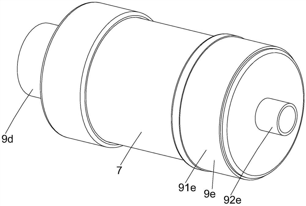
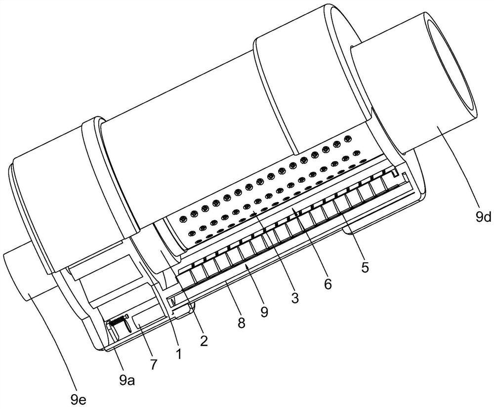
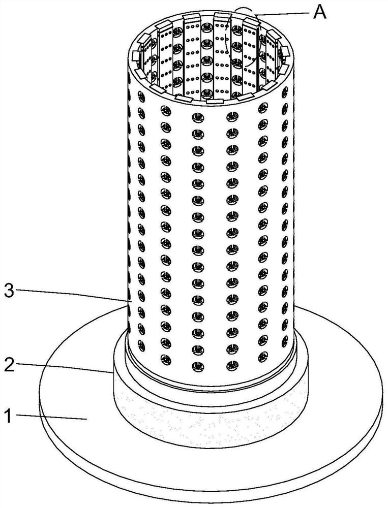
[0032] Such as Figure 1 to Figure 9 As shown, a compressor air filter element of the present invention includes a mounting plate 1, an inner bladder filter element 3, an outer bladder filter element 5 and a housing 8, and the housing 8 is fixedly installed on the mounting plate 1, and the housing 8 The outer gallbladder filter element 5 and the inner gallbladder filter element 3 are sleeved in the housing 8 and arranged coaxially with it, and the outer gallbladder filter element 5 sets the inner gallbladder filter element 3 in the outer gallbladder filter element 5 and is connected with the inner gallbladder The filter elements 3 are arranged concentrically.

[0033] In the specific implementation process, such as figure 2 , image 3 and Fi...


PUM


Abstract

The invention relates to the technical field of compressor accessories, in particular to a compressor air filter element. The compressor air filter element comprises a mounting plate, an inner container filter element piece, an outer container filter element piece and a shell. The inner container filter element piece is mounted in the mounting plate through a connecting seat. The outer container filter element piece is erected in the mounting plate and is fixedly mounted on the mounting plate through the shell, and the outer container filter element piece and the inner container filter elementpiece are sleeved with the shell and are arranged with the same axis as the shell. Because of protruding hollow blocks arranged in the inner container filter element piece, on one hand, the flow speed of air discharged out of filtration pores is slowed down, and on the other hand, secondary filtration is carried out on part of air to enable the part of air to be filtered better. Because of an extension mechanism, the flowing travel of the air is prolonged, and under the action of centrifugal force, the air in each layer of gap of a spiral piece diffuses more powerfully and further, the filtering efficiency of a filtering pipe is improved, and the dust suction force of carbon fiber sheets in the protruding hollow blocks is effectively increased.

Description

technical field [0001] The invention relates to the technical field of compressor accessories, in particular to a compressor air filter element. Background technique [0002] A compressor is a device used to compress gas, and the compressor is similar in structure to a water pump. Most compressors are reciprocating pistons, rotating blades or rotating screws, and an air filter is installed in the compressor. To inhale a large amount of air, if the air is not filtered, the dust suspended in the air will be inhaled, which will accelerate the wear of the components in the compressor. [0003] An existing air filter element used on a compressor includes two inner and outer cylinders with mesh holes, the top between the inner cylinder and the outer cylinder is provided with a top cover, and the middle part of the top cover is provided with a There is an air inlet, and there are multiple radially divergent carbon fiber sheets between the inner cylinder and the outer cylinder. The...

Claims


Application Information

Patent Timeline
Patent Type & Authority Applications(China)
IPC IPC(8): F04B39/16F04B37/12F04B39/00
CPCF04B37/12F04B39/00F04B39/16
Inventor 胡单陈伟
Owner 胡单
Learn More