Optimized furniture drawer illumination structure

A lighting structure and furniture technology, which is applied in household lighting, furniture parts, household appliances, etc. It can solve the problems of no lighting in the drawer, inconvenient use for users, and inability to quickly disassemble and assemble the drawer, so as to improve stability and facilitate daily maintenance. Effect

Pending Publication Date: 2020-12-11
GUANGDONG DTC HARDWARE PRECISION MFG CO LTD
View PDF1 Cites 4 Cited by
  • Summary
  • Abstract
  • Description
  • Claims
  • Application Information

AI Technical Summary

Problems solved by technology

[0003] The object of the present invention is to provide an optimized furniture drawer lighting structure to overcome the shortcomings of the prior art that the drawer has no lighting, which makes it inconvenient for users to use, and the drawer cannot be quickly disassembled and assembled.

Method used


Image

  • Optimized furniture drawer illumination structure
  • Optimized furniture drawer illumination structure
  • Optimized furniture drawer illumination structure

Examples


no. 1 example

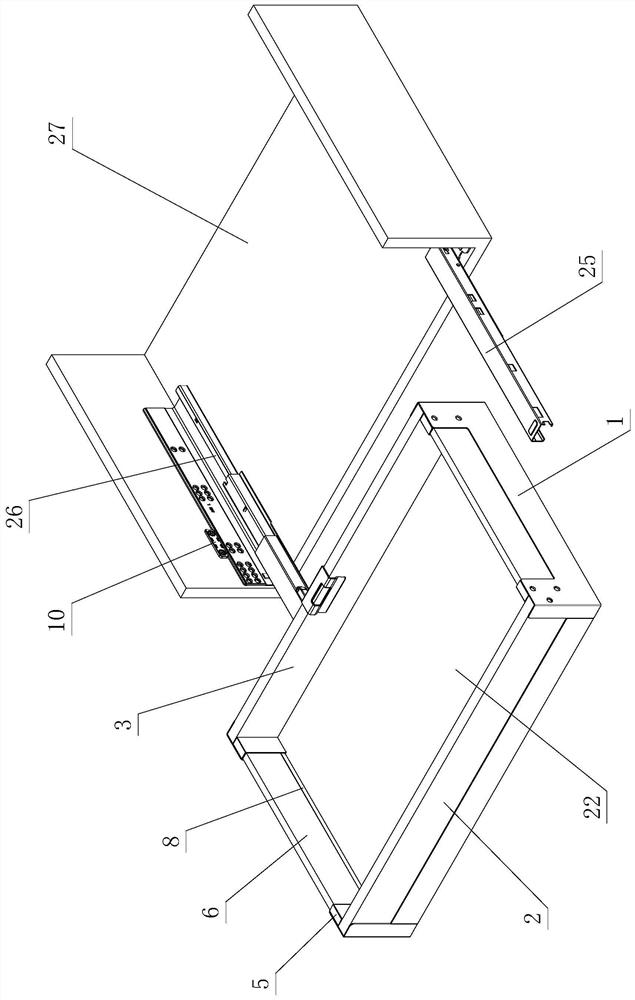
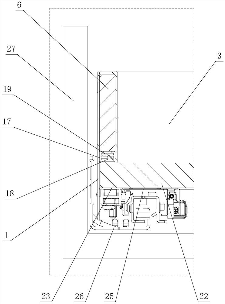
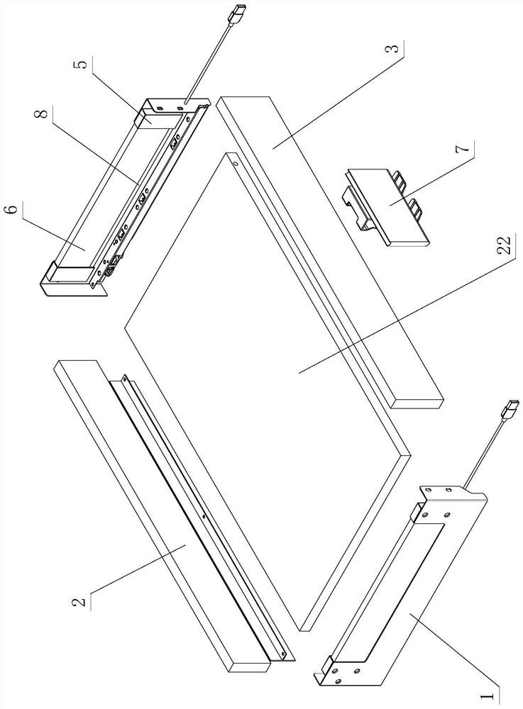
[0057] see Figure 1-Figure 11 , the optimized furniture drawer lighting structure includes a furniture drawer and a furniture fixed component that slide and cooperate with each other. The furniture drawer includes a side panel 1, a front panel 2 and a rear panel 3, and the side panel 1 is provided with a notch 4 and an adapter 5 and assembly plate 6.

[0058] The adapter piece 5 is fixedly arranged at the end of the side plate 1 .

[0059] The assembly plate 6 of this embodiment is arranged on the adapter piece 5 and is fixedly arranged on the notch portion 4 through the adapter piece 5 . The front board 2 and the rear board 3 are fixedly arranged on the side board 1 respectively.

[0060] A power supply component 7 is arranged on the furniture drawer.

[0061] In this embodiment, a light emitting assembly 8 is provided at the bottom of the assembly plate 6 , and the light emitting assembly 8 is electrically connected to the power supply component 7 and an electromagnetic ...

no. 2 example

[0085] see Figure 12-Figure 14 , the optimized furniture drawer lighting structure differs from the first embodiment in that: the mounting plate 6 is fixedly arranged on the notch 4 .

[0086] The front panel 2 is arranged on the adapter piece 5 and is fixedly arranged on the side panel 1 through the adapter piece 5 .

[0087] The rear plate 3 is fixedly arranged on the side plate 1 .

[0088] A light-emitting component 8 is arranged at the bottom of the front board 2 .

[0089] Specifically, the adapter piece 5 is in the shape of a line, and there are two left and right ones, which are respectively fixed on the front bending parts 13 of the left and right side panels 1 .

[0090] An assembly slot 15 is provided between the adapter piece 5 and the front bending portion 13 .

[0091] The front plate 2 can be directly arranged on the fitting groove 15 , and / or arranged on the fitting groove 15 through the elastic part 16 arranged in the fitting groove 15 . The front panel 2...

no. 3 example

[0098] see Figure 15-Figure 17 , the optimized furniture drawer lighting structure differs from the first embodiment in that: the assembly plate 6 is arranged on the adapter 5 and is fixedly arranged on the notch 4 through the adapter 5 .

[0099] The front panel 2 is arranged on the adapter piece 5 and is fixedly arranged on the side panel 1 through the adapter piece 5 .

[0100] The rear panel 3 is arranged on the adapter piece 5 and is fixedly arranged on the side panel 1 through the adapter piece 5 .

[0101] A light-emitting component 8 is arranged at the bottom of the assembly plate 6 , the front plate 2 , and the rear plate 3 .

[0102]Specifically, the adapters 5 are L-shaped, and there are four altogether. The four adapters 5 are arranged in front, back, left and right, and are respectively fixed on the front bending part 13, the front side wall 11, and the rear wall. On the bent portion 14 and the rear side wall 12 .

[0103] Fitting grooves 15 are provided betwe...


PUM


Abstract

The invention provides an optimized furniture drawer illumination structure. The structure comprises a furniture drawer and a furniture fixed assembly which are in sliding fit with each other, whereinthe furniture drawer comprises a side plate, a front plate and a rear plate, and a notch part, an adapter and an assembly plate part are arranged on the side plate; the adapter is arranged at the endpart of the side plate; the assembly plate part is arranged on the notch part, or is arranged on the adapter and is fixedly arranged on the notch part through the adapter; the front plate is fixedlyarranged on the side plate, or is arranged on the adapter and is fixedly arranged on the side plate through the adapter; the rear plate is arranged on the side plate, or is arranged on the adapter andis fixedly arranged on the side plate through the adapter; a power supply part is arranged on the furniture drawer; a light-emitting assembly is arranged at the bottom of the assembly plate part, and / or the front plate, and / or the rear plate, the light-emitting assembly is electrically connected with the power supply part, and an electromagnetic inductor is arranged on the light-emitting assembly; a magnet element is arranged on the furniture fixed assembly; and when the furniture drawer slides relative to the furniture fixed assembly to be opened and closed, the light-emitting assembly is controlled to emit light or be extinguished through electromagnetic induction of the electromagnetic inductor and the magnet element.

Description

technical field [0001] The invention relates to an optimized furniture drawer lighting structure. Background technique [0002] The Chinese patent literature number is CN204410146U, which discloses a drawer structure with increased capacity on June 24, 2015, which includes side panels, front panels, back panels, fixing devices and slide rail assemblies for opening and closing drawers, side panels A groove is arranged on the top, and the fixing device is assembled from more than three boards and more than two adapters through the connecting unit, and is arranged on the groove. It is said that the above-mentioned structure consists of three or more boards and two or more adapters assembled through the connecting unit to form a fixing device. Since the height difference is formed between adjacent boards and a concave shape is formed, the fixing device As the bottom plate of the drawer, the vertical space inside the drawer is increased without changing the original structure of...

Claims


Application Information

Patent Timeline
Patent Type & Authority Applications(China)
IPC IPC(8): F21S9/02F21V19/00F21V23/04F21V33/00A47B97/00F21W131/301
CPCA47B97/00A47B2220/0077F21S9/02F21V19/00F21V23/0471F21V33/0012F21W2131/301
Inventor 伍志勇
Owner GUANGDONG DTC HARDWARE PRECISION MFG CO LTD
Why Eureka
Try Eureka