
Air compressor cylinder body multi-hole machining device with auxiliary positioning mechanism

An auxiliary positioning and air compressor technology, applied in mechanical measuring devices, using mechanical devices, measuring devices, etc., can solve the problems of many uncontrollable factors, increased labor burden, and large error range, so as to improve air quality and reduce work. The effect of burden and error reduction

Active Publication Date: 2020-12-11
CHANGDE JIAHONG MACHINERY
View PDF8 Cites 0 Cited by
  • Summary
  • Abstract
  • Description
  • Claims
  • Application Information

AI Technical Summary

Problems solved by technology

[0003] However, it is necessary to position the cylinder block of the air compressor before drilling. Usually, the staff uses the measuring stick to measure and position. During the measurement of the measuring stick, it is necessary to ensure that it is in a horizontal state, which leads to too many uncontrollable factors when measuring the measuring stick. , the measurement error range is large, and manual measurement often requires multiple adjustments to accurately position the air compressor cylinder. Since the air compressor cylinder has a certain weight, it is difficult to carry it during multiple adjustments. Greatly increased the labor burden

Method used


Image

  • Air compressor cylinder body multi-hole machining device with auxiliary positioning mechanism
  • Air compressor cylinder body multi-hole machining device with auxiliary positioning mechanism
  • Air compressor cylinder body multi-hole machining device with auxiliary positioning mechanism

Examples


Embodiment 1

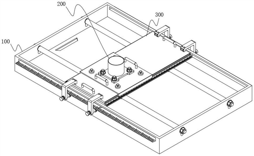
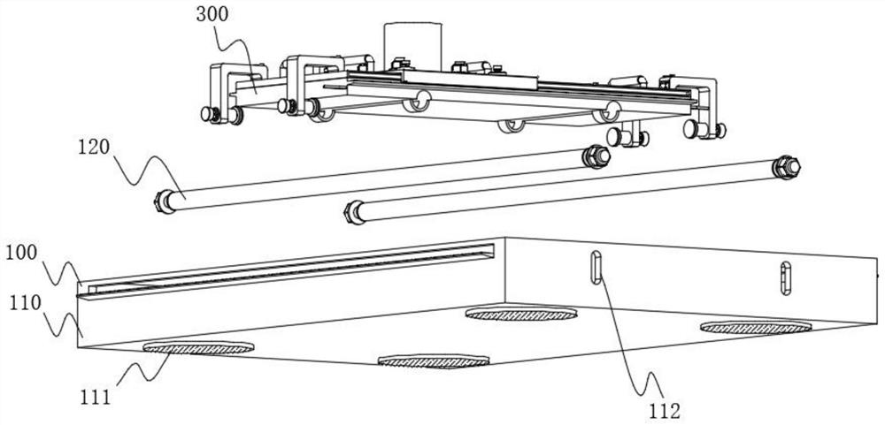
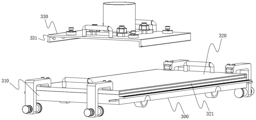
[0060] The invention provides an air compressor cylinder porous processing device with an auxiliary positioning mechanism, please refer to Figure 1-Figure 15 , including a support mechanism 100 and a cylinder body 200 arranged on the top of the support mechanism 100, the cylinder body 200 includes a mounting plate 210 fixed on its bottom, and mounting holes 211 are opened at the four corners of the mounting plate 210, and the mounting holes 211 are used for Cooperate with the bolts to install and fix the cylinder body 200. The support mechanism 100 includes a support seat 110. Two connection holes 112 are provided on the front and rear side walls of the support seat 110. A slide bar 120 is arranged between the front and rear connection holes 112. The two ends of the rod 120 are provided with connecting rods 121, and the connecting rods 121 are plugged and matched with the connecting holes 112. The left and right side walls of the support mechanism 100 are provided with bottom ...


PUM

PropertyMeasurementUnit
Thicknessaaaaaaaaaa
Thicknessaaaaaaaaaa
Thicknessaaaaaaaaaa

Abstract

The invention relates to the technical field of multi-hole machining, in particular to an air compressor cylinder multi-hole machining device with an auxiliary positioning mechanism. The device comprises a supporting mechanism and a cylinder body arranged at the top of the supporting mechanism, the supporting mechanism comprises a supporting base, two connecting holes are formed in each of the front side wall and the rear side wall of the supporting base, a sliding rod is arranged between the front connecting hole and the rear connecting hole, and connecting rods are arranged at the two ends of the sliding rod and matched with the connecting holes in an inserted mode; bottom pointer grooves are formed in the positions, close to the top, of the left and right side walls of the supporting mechanism, bottom scale plates are fixedly connected to the outer sides of the bottom pointer grooves, and auxiliary positioning mechanisms are arranged at the top of the supporting mechanism. Accordingto the invention, the positions of the bottom scale plate and the top scale plates and the positions of the bottom scale plates and the top scale plates are fixed and cannot move, so that uncontrollable factors are reduced, errors generated during measurement are reduced, and the auxiliary positioning accuracy of the auxiliary positioning mechanism is improved.

Description

technical field [0001] The invention relates to the technical field of porous processing, in particular to an air compressor cylinder porous processing device with an auxiliary positioning mechanism. Background technique [0002] The bottom of the air compressor cylinder is generally equipped with a mounting plate for installation. The four corners of the mounting plate are provided with mounting holes. The air compressor cylinder is installed and fixed through the mounting holes and bolts. Therefore, the general air compressor The cylinder body will be fixed with the mounting holes during the multi-hole machining to avoid deviation during drilling. [0003] However, it is necessary to position the cylinder block of the air compressor before drilling. Usually, the staff uses the measuring stick to measure and position. During the measurement of the measuring stick, it is necessary to ensure that it is in a horizontal state, which leads to too many uncontrollable factors when...

Claims


Application Information

Patent Timeline
IPC IPC(8): G01B5/02G01B5/00B01D46/00
CPCG01B5/02G01B5/0002B01D46/00
Inventor 谭宇岐铁钟王佩姿
Owner CHANGDE JIAHONG MACHINERY
Learn More