Circuit breaker interlocking switch device and safety low-voltage cabinet

A technology for interlocking switches and circuit breakers, which is applied to substations/switchgear boards/panels/desks, substations/switch layout details, electric switches, etc., which can solve the problems of high assembly precision requirements, poor device reliability, and difficult angle control and other issues to achieve good scalability, high security, and good reliability

Active Publication Date: 2020-12-11
HUIWANG ELECTRIC
View PDF10 Cites 2 Cited by
  • Summary
  • Abstract
  • Description
  • Claims
  • Application Information

AI Technical Summary

Problems solved by technology

The device uses the rotation of the movable pulley of the interlocking unit to drive the upper lever to rotate at a certain angle. When the rotation angle range of the upper lever reaches the angle for the emergency opening device to operate, the emergency opening device of the circuit breaker connected to the interlocking unit will act. The first circuit breaker cannot be closed; when the circuit breaker connected to any two interlocking units is closed, the closing signal of the two interlocking units drives the movable pulley of the third interlocking unit to rotate, so that the upper lever rotates at an angle of The angle at which the emergency opening device can be activated, so that any two circuit breakers can be closed, and the third circuit breaker cannot be closed. This patent has the advantages of simple structure and convenient disassembly and adjustment, but the emergency opening device can be activated through the angle range. In the actual operation process, the implementation method of the angle will have the disadvantages of difficulty in grasping the angle, poor reliability, and poor safety, and it requires high assembly precision of the device.
[0005] There is also a Chinese patent with a patent number of CN201387852Y that also discloses a similar interlock switch, but the structure involves certain uncontrollable factors, resulting in poor reliability of the device, which in turn affects safety.

Method used


Image

  • Circuit breaker interlocking switch device and safety low-voltage cabinet
  • Circuit breaker interlocking switch device and safety low-voltage cabinet
  • Circuit breaker interlocking switch device and safety low-voltage cabinet

Examples


Embodiment 1

[0025] Embodiment 1: A circuit breaker interlock switch device.

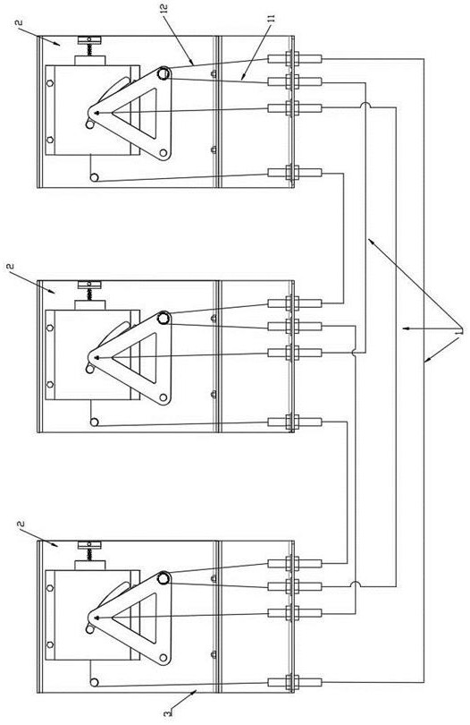
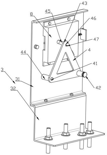
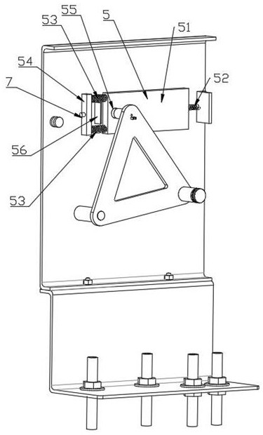
[0026] as attached Figure 1-5The shown circuit breaker interlock switch device includes three interlock units 2, and the interlock units 2 are respectively connected to the corresponding circuit breakers, and the interlock units 2 are connected by cables 1; An interlocking unit 2 includes a base plate 3 and a control part 4, a trigger part 5 and a guide plate 8 arranged on the base plate 3. The control part 4 includes a transmission end 41, a cable fixing end 42 and a limit end 43. The transmission end 41 is rotatably connected to the base plate 3 through the drive shaft 44 and is fixedly connected to the main shaft of the corresponding circuit breaker. The transmission end 41 is triggered to rotate by the opening / closing of the corresponding circuit breaker; the fixed end 42 of the cable is fixedly connected to the transmission end 41 and driven by the rotation of the transmission end 41, the cable fixed end ...

Embodiment 2

[0030] Embodiment 2: a safe low-voltage cabinet.

[0031] A safety low-voltage cabinet is provided with at least three circuit breakers, and the circuit breakers are provided with the circuit breaker interlock switch device described in Embodiment 1.

[0032] When the circuit breaker interlock switch device in the above two embodiments is in use, the opening and closing of the circuit breaker is transmitted to the control part 4 through the drive shaft 44 of the interlock unit, thereby driving the control part 4 to rotate clockwise or counterclockwise , when the circuit breaker is closed, the control part 4 rotates counterclockwise, the first cable 11 and the second cable 12 are pulled upward, and the second cable 12 drives the trigger part 5 of the next interlock unit to move to trigger the emergency switch switch, so that the corresponding circuit breaker cannot be closed; when the control part 4 is turned counterclockwise until the circuit breaker is in the closed state, th...


PUM


Abstract

The invention provides a circuit breaker interlocking switch device and a safety low-voltage cabinet, and belongs to the field of power distribution machinery interlocking, the interlocking switch device comprises a plurality of interlocking units, the interlocking units are respectively connected with corresponding circuit breakers, and the interlocking units are connected through ropes; each interlocking unit comprises a base plate, a control piece and a trigger piece, the control piece and the trigger piece are arranged on the base plate, opening and closing of the circuit breaker can drivethe control piece to rotate clockwise or anticlockwise, anticlockwise rotation of the control piece can drive the trigger piece of the next interlocking unit to move through a rope so as to trigger the emergency opening switch, and therefore the corresponding circuit breaker cannot be closed. Meanwhile, the control piece rotates anticlockwise to drive the elastic limiting rod of the previous interlocking unit to move through the rope so as to release the limitation of the control piece on the triggering piece, and the basic requirement of 'two-in-one opening' is met through the limitation ofthe control piece on the triggering piece and the linkage between the adjacent interlocking units; and meanwhile, the operation of the interlocking device is more stable and accurate through the optimization of the structure.

Description

technical field [0001] The invention belongs to the field of power distribution machinery interlocking, in particular relates to a circuit breaker interlocking switch device, in particular to a safety low-voltage cabinet using the interlocking switch device. Background technique [0002] The power supply and distribution system is one of the core contents of electrical design. Even if the high-voltage power supply is taken from the same bus section, in order to limit the short-circuit capacity of the system and prevent parallel operation of transformers, interlocking between transformer low-voltage bus sections is also required. Therefore, after the power source and load are determined, the interlocking mode of the low-voltage power distribution system becomes an important factor affecting the system wiring scheme. [0003] In the low-voltage power distribution system, the low-voltage power distribution method in which two power supplies are used in the middle is a bus tie c...

Claims


Application Information

Patent Timeline
Patent Type & Authority Applications(China)
IPC IPC(8): H01H71/10H01H9/20H01H9/26H02B1/32H02B1/04
CPCH01H9/20H01H9/26H01H71/1009H01H2009/265H02B1/04H02B1/32
Inventor 徐峰梁意珍徐顺山
Owner HUIWANG ELECTRIC
Why Eureka
Try Eureka