
Display panel and display device

A display panel and display area technology, which is applied in the direction of identification devices, instruments, etc., can solve the problems of affecting the display effect and the large difference in the resistance of data lines, and achieve the effects of uniform charging, balanced resistance, and improved display effect

Inactive Publication Date: 2020-12-11
YUNGU GUAN TECH CO LTD
View PDF5 Cites 6 Cited by
  • Summary
  • Abstract
  • Description
  • Claims
  • Application Information

AI Technical Summary

Problems solved by technology

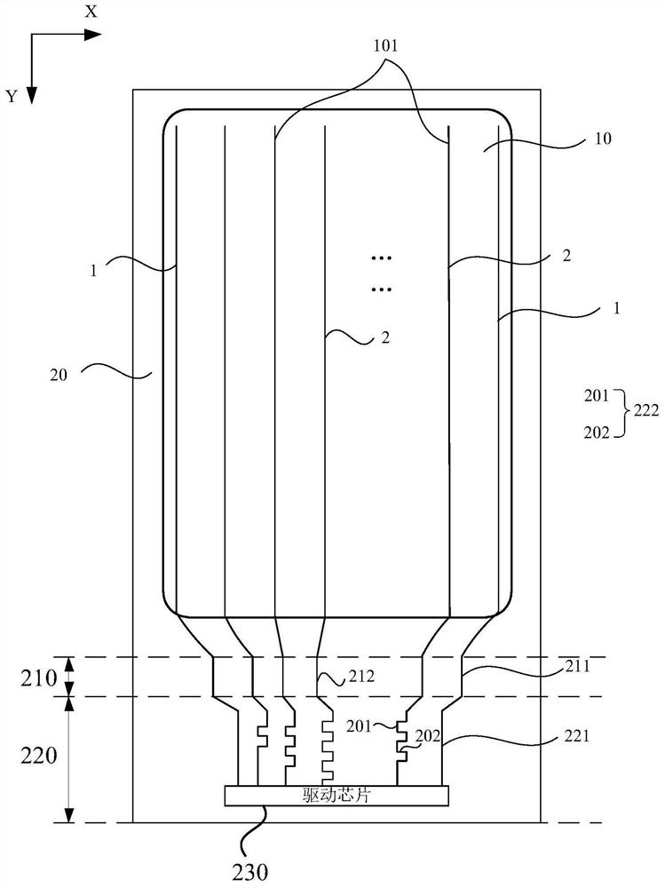
[0004] Embodiments of the present invention provide a display panel and a display device to solve the problem in the prior art that the resistance of each data line is greatly different, which affects the display effect

Method used


Image

  • Display panel and display device
  • Display panel and display device
  • Display panel and display device

Examples


Embodiment Construction

[0030] The present invention will be further described in detail below in conjunction with the accompanying drawings and embodiments. It should be understood that the specific embodiments described here are only used to explain the present invention, but not to limit the present invention. In addition, it should be noted that, for the convenience of description, only some structures related to the present invention are shown in the drawings but not all structures.

[0031] As described in the background technology, after the data lines in the prior art are drawn out from the display area, they pass through the non-display area, generally through the lower frame area of ​​the display panel, and are connected to the pads (also called pads, welding pads) located in the non-display area. etc.), the pad is used to bind the driver chip or chip-on-chip to transmit the display drive signal to the data line, and the non-display area will also be provided with a power line. During the w...


PUM


Abstract

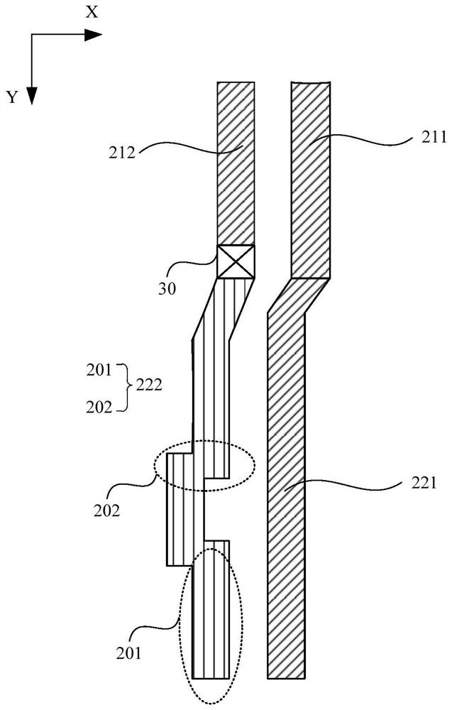
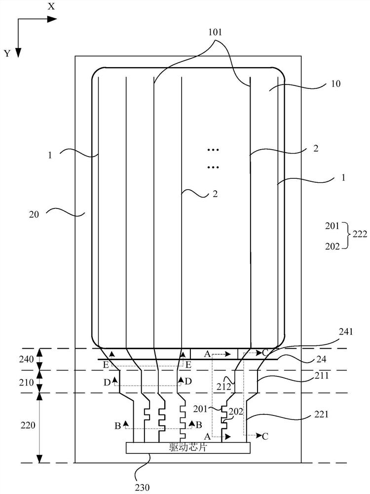
The embodiment of the invention discloses a display panel and a display device. The display panel comprises a plurality of data lines extending from a fan-out area to a display area through a bendingarea, the data lines comprise a plurality of first wires and a plurality of second wires, and the areas where the first wires are located are distributed on the two sides of the areas where the secondwires are located; each first wire comprises a first metal section located in the fan-out area and a second metal section located in the bending area; each second wire comprises a third metal sectionlocated in the fan-out area and a fourth metal section located in the bending area; and the length of each third metal section is larger than that of the corresponding first metal section, and the resistivity of each third metal section is larger than that of the corresponding first metal section. According to the technical scheme, the resistance difference between the data lines on the edge of the display panel and the data lines in the center area can be reduced, so that charging is more uniform, and then the display effect of the display panel is improved.

Description

technical field [0001] Embodiments of the present invention relate to the field of display technology, and in particular, to a display panel and a display device. Background technique [0002] With the development of display technology, users have higher and higher requirements for display panels, and for high-end display panels, designs with narrow borders are becoming more and more popular. [0003] At present, for high-end small and medium-sized screens, the data lines are led out from the display area and then connected to the driver chip or chip-on-chip film. In the prior art, due to the different distances between the data lines and the driving chip, the length of the data lines forming the edge of the display area is much longer than the length of the data lines forming the data lines in the central area of ​​the display area, resulting in resistance on each data line. If the difference is large, it is easy to reduce the display uniformity, thereby reducing the displ...

Claims


Application Information

Patent Timeline
Patent Type & Authority Applications(China)
IPC IPC(8): G09F9/30
CPCG09F9/30
Inventor 卓然然盖翠丽王玲
Owner YUNGU GUAN TECH CO LTD
Learn More