Wiper for machine tool
A technology of cutting tools and cleaners, which is applied in the direction of manufacturing tools, metal processing equipment, metal processing machinery parts, etc., can solve the problems of spring steel corrosion and damage to sliding surfaces, etc., and achieve small frictional resistance, fast sliding work, and reduced wear effect
- Summary
- Abstract
- Description
- Claims
- Application Information
AI Technical Summary
Problems solved by technology
Method used
Image
Examples
example 1
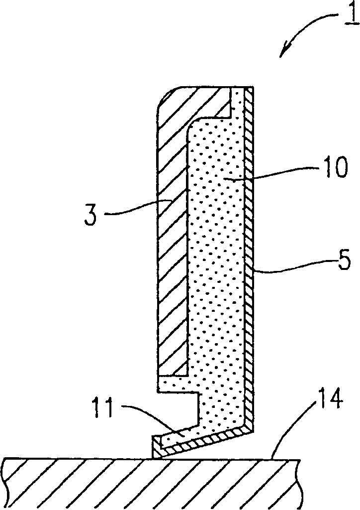
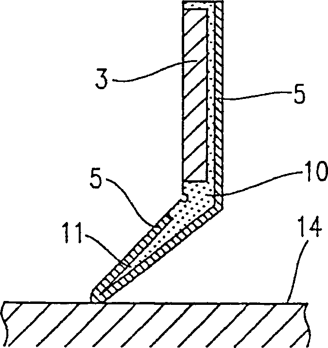
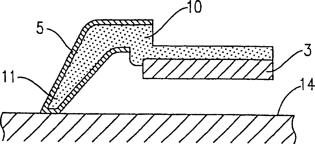
[0079] A rod with a core and a woven fabric made of synthetic fibers are placed in the mould. The mold was filled with unvulcanized NBR and subsequently vulcanized. As a result, get as figure 1 Shown is a wiper 1 comprising a cored rod 3 and a wiper body 10 . The lip 11 of the wiper body 10 is covered with the organic fabric 5 .
[0080] Use wiper 1 and measure pressure, sliding resistance, and amount of spilled debris. The results are shown in Table 1.
[0081] wiper type
Measurement items
Comparative example 1
Comparative example 2
Example 1
Pressure (gf / cm)
133
50
181
Sliding resistance (gf / cm)
71
19
48
in the slide test
amount of debris leaked
(g)
5km trip
0.06
0.10
0.05
15km trip
0.12
0.16
0.09
30km trip
0.25
0.19
0.11
[0082] The results shown in Table 1 indicate the following:
[0083] In Comparative Example 1, ...
example 2
[0087] The cored rod and the woven fabric made of synthetic fibers (nylon 6,6) are placed in a mold filled with unvulcanized NBR and subsequently vulcanized. As a result, get as Figure 10 Shown is a wiper 1 comprising a cored rod 3 and a wiper body 10 . The sliding surface of the lip 11 of the wiper body 10 is covered with the organic fabric 5 .
[0088] The woven fabric used has a thickness of 0.5 mm (measured on the original fabric). The weft yarn of the woven fabric has a fineness of 100 denier and the warp yarn of the woven fabric has a fineness of 50 denier. The woven fabric is arranged on the lower surface of the lip so that the weft yarns are arranged perpendicular to the sliding direction.
[0089] This wiper was used, and its frictional resistance was measured under the following conditions.
[0090] A. Test method:
[0091] use Image 6 in the test equipment. exist Image 6 In , reference numeral 7 designates a support, reference numeral 1 designates a wiper...
example 3
[0101] The thickness of the fabric material (the original fabric to be used for the fabric layer) was 1.0 mm, and the weft yarn of the fabric material had a fineness of 420 denier, and the warp yarn of the fabric material had a fineness of 210 denier. In other respects, the wiper of Example 3 is the same as that of Example 2. The frictional resistance of the wiper of Example 3 was measured.
[0102] As a result, the distance over which the wiper was operated until abnormal noise was generated was 2000 km.
PUM
 Abstract
Description
Claims
Application Information
 - R&D
- Intellectual Property
- Life Sciences
- Materials
- Tech Scout
- Unparalleled Data Quality
- Higher Quality Content
- 60% Fewer Hallucinations
Browse by: Latest US Patents, China's latest patents, Technical Efficacy Thesaurus, Application Domain, Technology Topic, Popular Technical Reports.
© 2025 PatSnap. All rights reserved.Legal|Privacy policy|Modern Slavery Act Transparency Statement|Sitemap|About US| Contact US: help@patsnap.com


