Machining die for pressure sensor

A technology for pressure sensors and processing molds, which is applied to forming tools, manufacturing tools, metal processing equipment, etc., can solve the problems of slow heat dissipation progress and difficult removal of the shell, and achieve the effect of improving production efficiency, simple structure, and speeding up heat dissipation progress.

Inactive Publication Date: 2020-12-15
杨光明
View PDF0 Cites 0 Cited by
  • Summary
  • Abstract
  • Description
  • Claims
  • Application Information

AI Technical Summary

Problems solved by technology

[0003] The purpose of the present invention is to solve the problems in the prior art that the progress of heat dissipation is slow and the shell is not easy to take out after the stamping is completed, and a processing mold for a pressure sensor is proposed.

Method used


Image

  • Machining die for pressure sensor
  • Machining die for pressure sensor
  • Machining die for pressure sensor

Examples


Embodiment 1

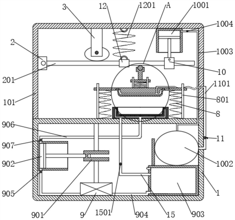
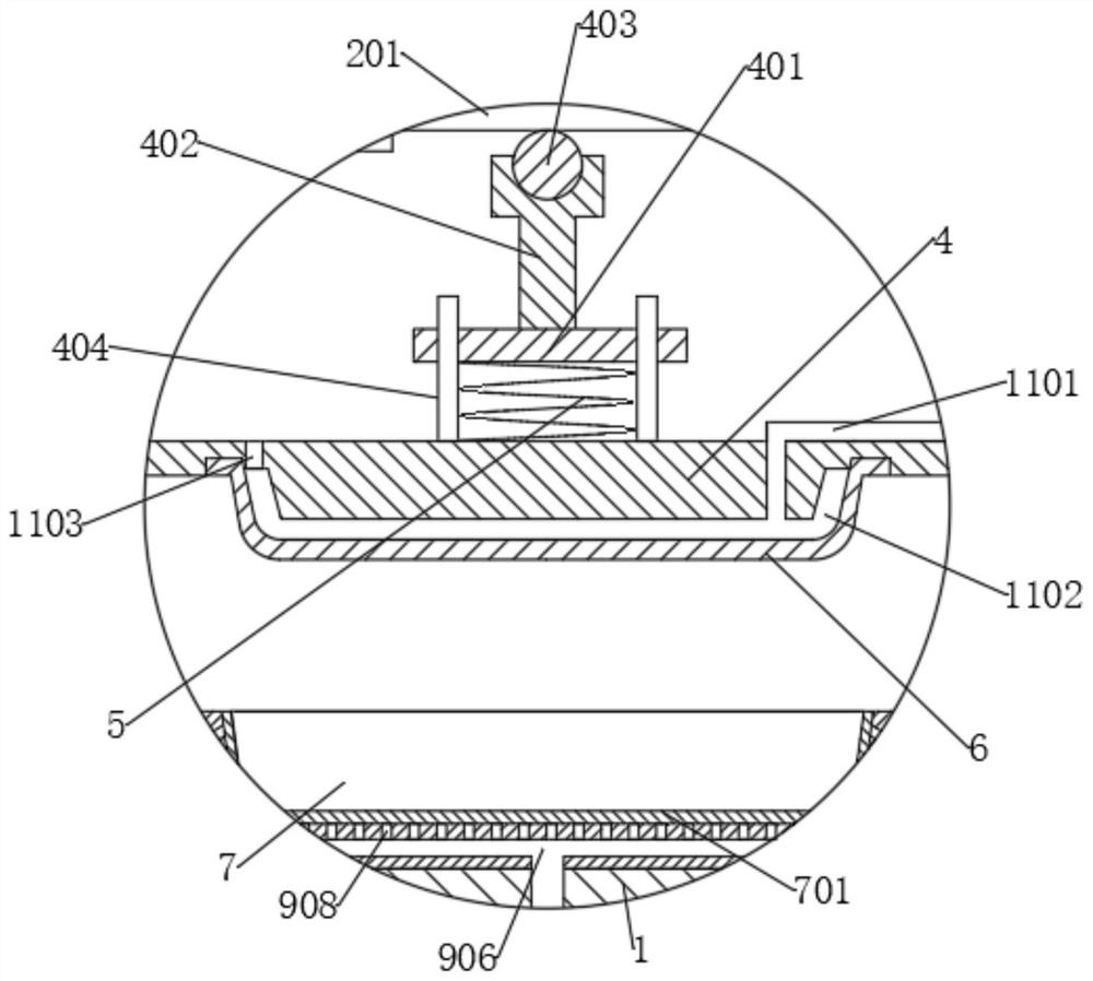
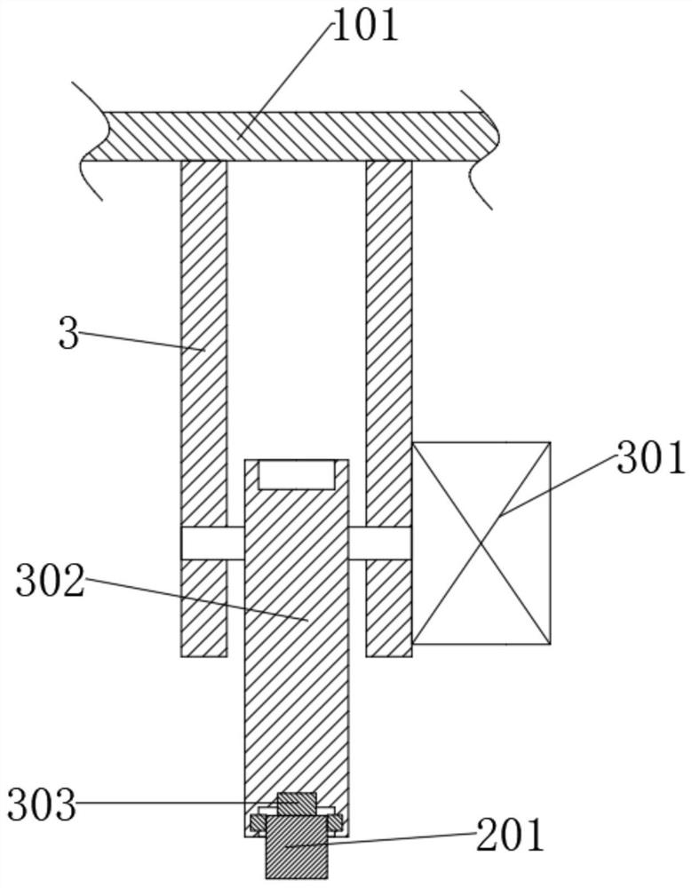
[0027] refer to Figure 1-4 , a processing mold for a pressure sensor, comprising a first box body 1 and a second box body 101, the second box body 101 is located at the top of the first box body 1, and a rotating rod 201 is rotatably connected in the second box body 101, the first box body 101 The top of the box body 1 is provided with a second spring 8, and the end of the second spring 8 far away from the first box body 1 is connected with a second connecting plate 4, and the second connecting plate 4 is provided with a push rod 402, and the push rod 402 and the rotating rod 201 Cooperate with each other, the bottom of the second connecting plate 4 is provided with an upper mold 6, the top of the first box 1 is provided with a lower mold 7, the lower mold 7 is provided with oil paper 701, and the first box 1 is respectively provided with a second motor 9, The first piston 902 and the oil tank 903, the output end of the second motor 9 is connected to the crankshaft 901, the c...

Embodiment 2

[0039] refer to Figure 1-4 , a processing mold for a pressure sensor, comprising a first box body 1 and a second box body 101, the second box body 101 is located at the top of the first box body 1, and a rotating rod 201 is rotatably connected in the second box body 101, the first box body 101 The top of the box body 1 is provided with a second spring 8, and the end of the second spring 8 far away from the first box body 1 is connected with a second connecting plate 4, and the second connecting plate 4 is provided with a push rod 402, and the push rod 402 and the rotating rod 201 Cooperate with each other, the bottom of the second connecting plate 4 is provided with an upper mold 6, the top of the first box 1 is provided with a lower mold 7, the lower mold 7 is provided with oil paper 701, and the first box 1 is respectively provided with a second motor 9, The first piston 902 and the oil tank 903, the output end of the second motor 9 is connected to the crankshaft 901, the c...


PUM


Abstract

The invention discloses a machining die for a pressure sensor, and belongs to the technical field of sensor dies. The machining die for the pressure sensor comprises a first box body and a second boxbody. The second box body is located at the top of the first box body; a rotating rod is rotatably connected in the second box body; second springs are arranged at the top of the first box body; a second connecting plate is connected with the ends, away from the first box body, of the second springs; a pushing rod is arranged on the second connecting plate; the pushing rod is matched with the rotating rod; an upper mold is arranged at the bottom of the second connecting plate; a lower mold is arranged at the top of the first box body; oil paper is arranged inside the lower mold; and a second motor, a first piston, and an oil tank are respectively arranged inside the first box body. The machining die for the pressure sensor is simple in structure and convenient to operate, the problem thata shell is not easy to take out is solved through mutual cooperation of the first piston and the oil tank, and the heat dissipation progress is accelerated through mutual cooperation of an air bag anda heat dissipation holes, so that the production efficiency is greatly improved.

Description

technical field [0001] The invention relates to the technical field of sensor molds, in particular to a processing mold for a pressure sensor. Background technique [0002] A pressure sensor is a device or device that can sense pressure signals and convert the pressure signals into usable output electrical signals according to certain rules. Pressure sensors are usually composed of pressure sensitive elements and signal processing units. According to different test pressure types, Pressure sensors can be divided into gauge pressure sensors, differential pressure sensors and absolute pressure sensors. Pressure sensors are the most commonly used sensors in industrial practice. They are widely used in various industrial self-control environments. At present, pressure sensor housings need to be Manufacturing with a processing mold, when stamping the shell, the progress of heat dissipation is slow, and after the stamping is completed, the shell is not easy to take out, resulting ...

Claims


Application Information

Patent Timeline
Patent Type & Authority Applications(China)
IPC IPC(8): B21D37/10B21D37/12B21D37/16B21D37/18
CPCB21D37/10B21D37/12B21D37/16B21D37/18
Inventor 杨光明
Owner 杨光明
Why Eureka
Try Eureka