Full-automatic steel bar twisting device

A fully automatic, torsion-type technology, applied in the field of torsion-type equipment, can solve the problems of large volume and single function

Pending Publication Date: 2020-12-15
康建霞
View PDF6 Cites 7 Cited by
  • Summary
  • Abstract
  • Description
  • Claims
  • Application Information

AI Technical Summary

Problems solved by technology

[0004] In order to overcome the shortcomings of existing equipment, such as large volume and single function, the purpose of this invention is to provide a fully automatic steel bar twisting equipment that can realize small volume, light transportation, automatic bending and blanking.

Method used


Image

  • Full-automatic steel bar twisting device
  • Full-automatic steel bar twisting device
  • Full-automatic steel bar twisting device

Examples


Embodiment 1

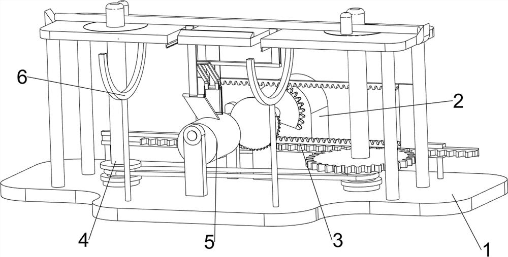
[0053] A fully automatic steel bar twisting equipment, such as figure 1 As shown, it includes a base 1, a geared motor 2, a transmission mechanism 3 and a twisting mechanism 4. The geared motor 2 is connected in the middle of the top rear side of the base 1, and the transmission mechanism 3 is connected between the base 1 and the output shaft of the geared motor 2. The base 1 A torsion mechanism 4 is connected with the transmission mechanism 3 .

[0054] When people need to bend the steel bar, the steel bar is first placed on the parts of the twist mechanism 4, then the gear motor 2 is started, and the output shaft of the gear motor 2 rotates to drive the parts of the transmission mechanism 3 to move, so that the parts of the twist mechanism 4 are opposite to the steel bar. Bending is carried out at both ends, and after completion, turn off the reduction motor 2 and take out the reinforcing bar.

Embodiment 2

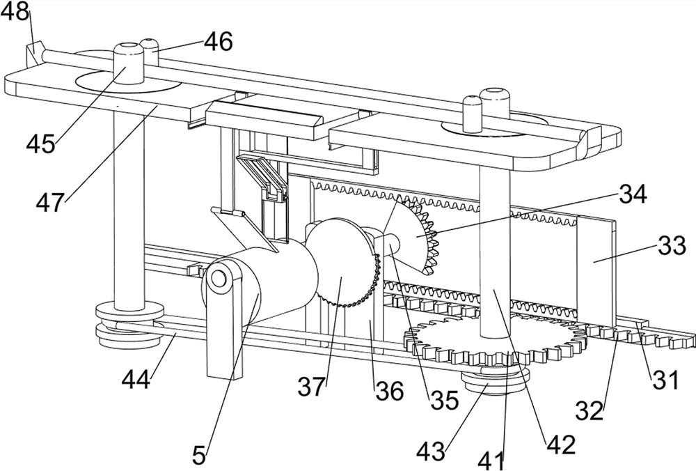
[0056] On the basis of Example 1, such as figure 2 As shown, the transmission mechanism 3 includes a first card slot 31, a spur rack 32, a built-in spur rack 33, a first rotating shaft 35, a first missing gear 34, a first support rod 36 and a second missing gear 37, the base 1 A first card slot 31 is connected between the left and right sides of the rear part, and a spur rack 32 is slidably connected in the first card slot 31, and the spur rack 32 is engaged with the parts of the twist mechanism 4, and the top of the spur rack 32 is connected The spur rack 33 is attached inside, the first support rod 36 is connected in the middle of the rear side of the base 1, the first support rod 36 is located on the front side of the geared motor 2, the upper part of the first support rod 36 is rotatably connected with the first rotating shaft 35, and the first rotating shaft 35 rear sides are connected with the first missing gear 34, the first missing gear 34 rear side is connected with ...

Embodiment 3

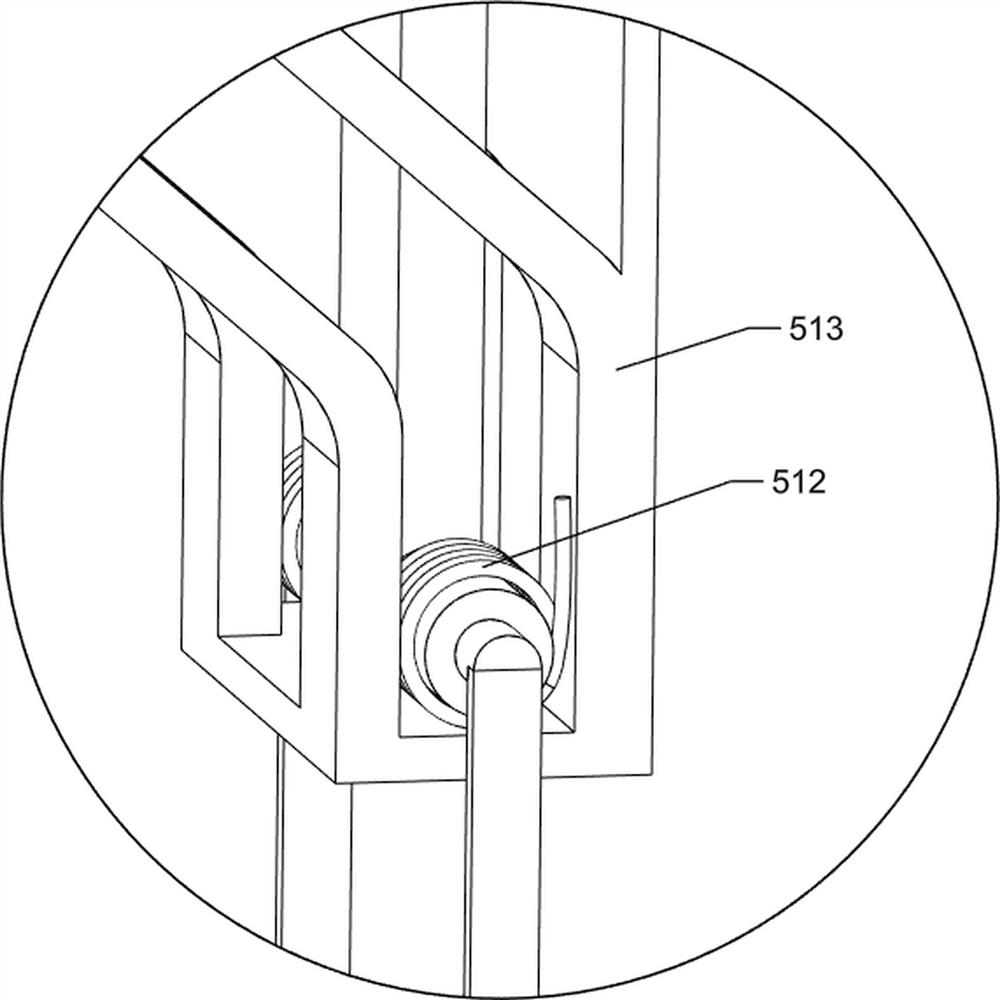
[0061] On the basis of Example 2, such as Figure 3-5 As shown, a pusher mechanism 5 is also included, and the pusher mechanism 5 includes a second support rod 501, a third rotating shaft 502, a second gear 503, a cam 504, a push rod 505, a grooved bracket 506, a cylindrical slide block 507, The second draw-in slot 508, the fixed rod 509, the inclined push plate 510, the third draw-in slot 511, the torsion spring 512 and the fourth draw-in slot 513, the base 1 is connected with the second support bar 501 on the left side, the front and rear sides, the second A third rotating shaft 502 is rotatably connected between the upper parts of the support rods 501, the second gear 503 is connected to the rear of the third rotating shaft 502, the second gear 503 meshes with the second missing gear 37, and a cam 504 is connected to the front of the third rotating shaft 502 , the left rear part of the bottom of the torsion table 47 is connected with a fourth card slot 513, the fourth card ...


PUM


Abstract

The invention relates to a twisting device, in particular to a full-automatic steel bar twisting device. The full-automatic steel bar twisting device is small in size, light and convenient to transport and capable of achieving automatic bending and discharging during operation. The full-automatic steel bar twisting device comprises a base, a gear motor, a transmission mechanism and a twisting mechanism, and one side of the top of the base is connected with the gear motor, Through cooperation of the gear motor, the transmission mechanism and the twisting mechanism, after people manually place steel bars on a twisting table, the steel bars are automatically bent through the transmission mechanism and the twisting mechanism, the steel bars do not need to be manually fixed in the bending process, and time and labor are saved. After the steel bars are successfully bent, the bent steel bars can be pushed forwards through a pushing mechanism, and a collecting mechanism can facilitate people to collect the bent steel bars.

Description

technical field [0001] The invention relates to a twisting device, in particular to a fully automatic steel bar twisting device. Background technique [0002] At present, steel bars play an important role in the construction industry, and in the process of using steel bars, it is also necessary to bend steel bars into shapes required by various workers. Usually, it is necessary to use the steel bar twisting machine to bend the steel bar to meet the needs of house construction. In actual use, for the convenience of use, people usually transport the steel bar twisting machine to the building construction site for the steel bar twisting operation, so as to improve the housing construction. construction efficiency. [0003] However, the steel bar twisting machine currently used for house construction usually does not have a good moving mechanism. It is troublesome during the moving process and is not convenient for people to use. This kind of steel bar bending machine has a sin...

Claims


Application Information

Patent Timeline
Patent Type & Authority Applications(China)
IPC IPC(8): B21F1/00
CPCB21F1/00
Inventor 康建霞
Owner 康建霞
Why Eureka
Try Eureka