Push-pull scanning grating

A scanning grating and push-pull technology, which is applied in the field of micro-opto-electromechanical systems, can solve the problems of large volume and high power consumption, and achieve the effects of low process complexity, simple structure and low power consumption

Pending Publication Date: 2020-12-15
CISDI RES & DEV CO LTD
View PDF0 Cites 1 Cited by
  • Summary
  • Abstract
  • Description
  • Claims
  • Application Information

AI Technical Summary

Problems solved by technology

[0006] In view of the above existing problems in the prior art, the present invention proposes a push-pull scanning grating, which mainly solves the problems of high power consumption and large volume of the existing unipolar driving method

Method used


Image

  • Push-pull scanning grating
  • Push-pull scanning grating
  • Push-pull scanning grating

Examples


Embodiment Construction

[0025] The embodiments of the present invention are described below through specific specific examples, and those skilled in the art can easily understand other advantages and effects of the present invention from the contents disclosed in this specification. The present invention can also be implemented or applied through other different specific embodiments, and various details in this specification can also be modified or changed based on different viewpoints and applications without departing from the spirit of the present invention. It should be noted that the following embodiments and features in the embodiments may be combined with each other under the condition of no conflict.

[0026] It should be noted that the drawings provided in the following embodiments are only used to illustrate the basic concept of the present invention in a schematic way, so the drawings only show the components related to the present invention rather than the number, shape and number of compo...


PUM


Abstract

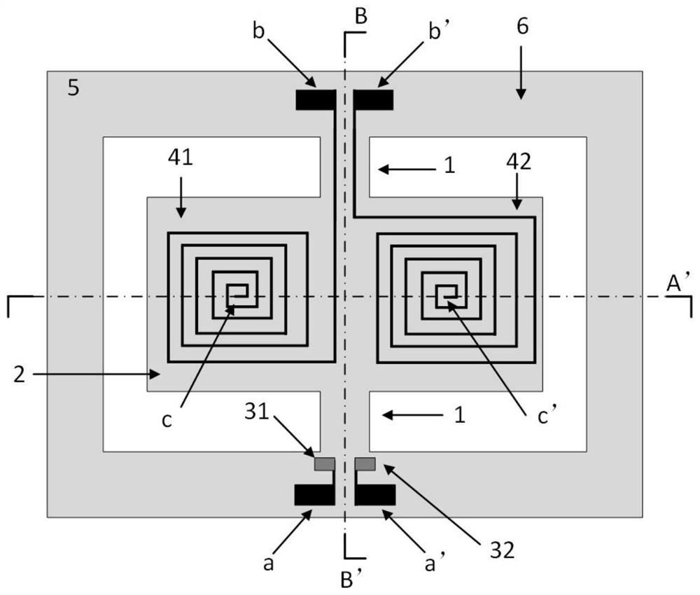
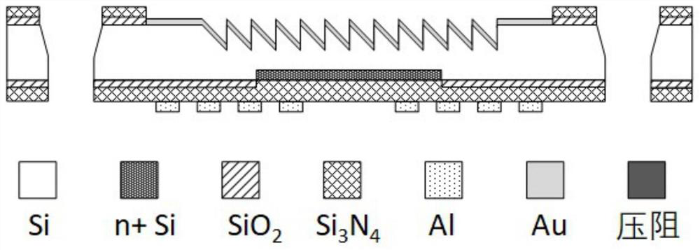
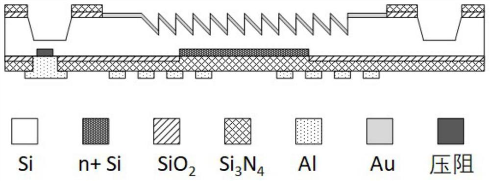
The invention provides a push-pull scanning grating, which is characterized by comprising a supporting frame, a reflection grating, a torsion beam, an electromagnetic push-pull driver used for drivingthe reflection grating to be twisted and an angle sensor used for detecting the twisting angle of the grating, wherein the reflecting grating is connected with the supporting frame through two torsion beams which are distributed on the two side edges and are symmetrically arranged; the axes of the two torsion beams coincide with the center line of the side edge of the reflection grating; the angle sensor is arranged at the joint of one of the torsion beams and the supporting frame; the electromagnetic push-pull driver comprises a driving coil and two driving electrodes; and driving signals are input through the driving electrodes, driving coils arranged on the two side edges of the center line of the reflection grating are controlled to form currents with opposite flow directions, and thereflection grating is driven to twist. According to the invention, the structure is simple, the power consumption can be effectively reduced, and the stability of the scanning grating is enhanced.

Description

technical field [0001] The invention relates to the technical field of micro-optical electromechanical systems, in particular to a push-pull scanning grating. Background technique [0002] As one of the important devices of micro-optical electromechanical systems (MOEMS), scanning gratings have been widely used in portable intelligent monitoring, food safety, chemical detection and other fields. The basic principle is: process the grating mirror surface that meets the ultraviolet requirements through MEMS technology, accurately control the driving force of the grating rotation, and combine the angle feedback of the angle sensor to accurately control the rotation angle of the grating mirror surface, so as to achieve precise control of the grating scan. [0003] At present, most of the scanning gratings are driven by electrostatic, electrothermal and piezoelectric driving principles. Electrostatic driving can only apply attractive driving force, so it is usually only possible...

Claims


Application Information

Patent Timeline
Patent Type & Authority Applications(China)
IPC IPC(8): G02B26/10G02B7/00
CPCG02B26/106G02B7/00
Inventor 姜森林何文馨漆锐冯科杨玉
Owner CISDI RES & DEV CO LTD
Why Eureka
Try Eureka