Electromagnetically driven two-dimensional scanning micromirrors for laser scanning display

An electromagnetic drive, laser scanning technology, applied in piezoelectric/electrostrictive/magnetostrictive devices, microstructure devices composed of deformable elements, optics, etc. , mirror distortion, etc.

Active Publication Date: 2017-09-29
苏州工业园区纳米产业技术研究院有限公司
View PDF1 Cites 0 Cited by
  • Summary
  • Abstract
  • Description
  • Claims
  • Application Information

AI Technical Summary

Problems solved by technology

There is an electromagnetic coil directly on the mirror, which is easy to deform the mirror surface, and increases the area and mass of the mirror, so it is relatively difficult to achieve high-frequency torsion
A cantilever beam with an electromagnetic coil drives the mirror to twist around the X-axis. The cantilever beam is directly connected to the torsion universal joint, and is far away from the torsion axis. The structural constraints make it difficult for the mirror to obtain a large twist angle.

Method used


Image

  • Electromagnetically driven two-dimensional scanning micromirrors for laser scanning display
  • Electromagnetically driven two-dimensional scanning micromirrors for laser scanning display
  • Electromagnetically driven two-dimensional scanning micromirrors for laser scanning display

Examples


Embodiment Construction

[0025] The specific embodiments of the present invention will be described in further detail below in conjunction with the drawings and embodiments. The following examples are used to illustrate the present invention, but not to limit the scope of the present invention.

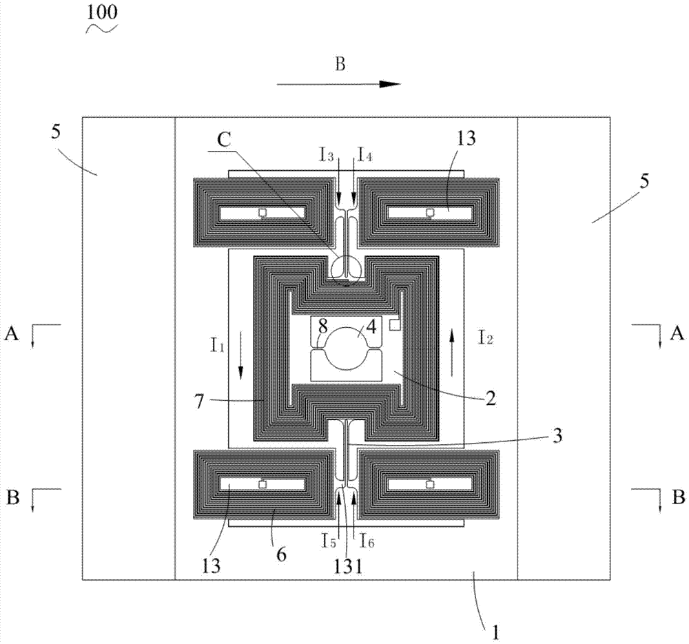
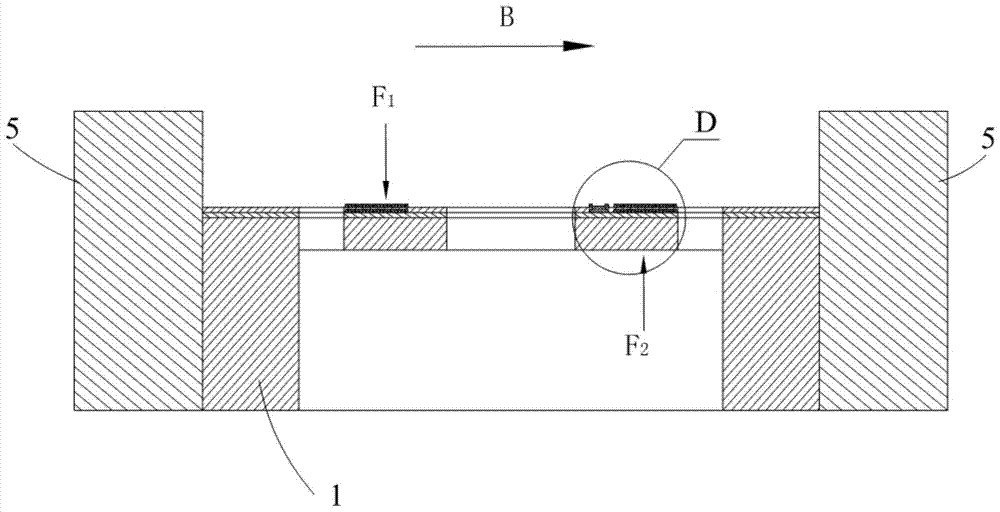
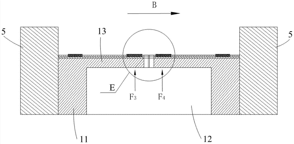
[0026] See Figure 1 to Figure 6 , An electromagnetically driven two-dimensional scanning micromirror 100 for laser scanning display (hereinafter referred to as a micromirror) according to a preferred embodiment of the present invention includes a peripheral frame 1, an inner frame 2 arranged in the peripheral frame 1, and a connection The vertical scanning torsion beams 3 of the outer frame 1 and the inner frame 2, the micro mirror 4 and a pair of magnets 5 arranged in the inner frame 2. The peripheral frame 1 has a frame 11, a cavity 12 surrounded by the frame 11, and a cantilever 13 straddling the cavity 12. The inner frame 2 is connected to the peripheral frame 1 through a vertical scanning torsion beam 3 ...


PUM


Abstract

The invention relates to an electromagnetically driven two-dimensional scanning micromirror for laser scanning display, which comprises an outer frame, an inner frame arranged in the outer frame, a vertical scanning torsion beam connecting the outer frame and the inner frame, and an inner frame arranged The inner micro-mirror and a pair of magnets, the outer frame has a cantilever, the inner frame is connected to the cantilever of the outer frame through a vertical scanning torsion beam, the cantilever driving coil is arranged on the cantilever, and the inner frame driving coil is arranged on the inner frame. The magnets are respectively arranged on both sides of the cantilever. The magnetic field lines generated by the magnets are perpendicular to the current direction of the cantilever drive coil and the inner frame drive coil. The mutual interference between the two directions is reduced, and a large torsion angle can be easily obtained. In addition, the utilization rate of the magnetic field can be improved, and the driving scheme is simplified.

Description

Technical field [0001] The invention relates to an electromagnetically driven two-dimensional scanning micromirror for laser scanning display. Background technique [0002] Laser scanning display technology refers to the use of movable mirrors to complete horizontal and vertical laser beam scanning to form a scanned image on the screen. The scanning method is similar to that of a traditional cathode ray tube (CRT, Cathode Ray Tube) TV. The difference is The electron beam is replaced by a laser beam. In order to achieve high-resolution images, the scanning frequency (line frequency) of the micromirror in the horizontal direction needs to be above 20KHz, and the scanning frequency (frame frequency) in the vertical direction is generally 60Hz. Laser scanning display technology uses RGB three primary color laser beams to form color images, resulting in a wider color gamut and more vivid colors. Due to the characteristics of laser, undistorted images can be displayed on any shape su...

Claims


Application Information

Patent Timeline
Patent Type & Authority Patents(China)
IPC IPC(8): G02B26/08G02B26/10B81B3/00
Inventor 李文翔
Owner 苏州工业园区纳米产业技术研究院有限公司
Why Eureka
Try Eureka