Transformer rubber-coated metal winding and rubber coating method thereof

A technology of transformers and metals, applied in the direction of transformer/inductor coil/winding/connection, transformer/inductor parts, inductor/transformer/magnet manufacturing, etc., which can solve problems such as no temperature grade requirements, limited use range, short circuit, etc. , to achieve good safety performance, solve the problem of not being able to withstand high pressure, and simple operation steps

Active Publication Date: 2020-12-15
WURTH ELECTRONICSCHONGQING +1
View PDF11 Cites 0 Cited by
  • Summary
  • Abstract
  • Description
  • Claims
  • Application Information

AI Technical Summary

Problems solved by technology
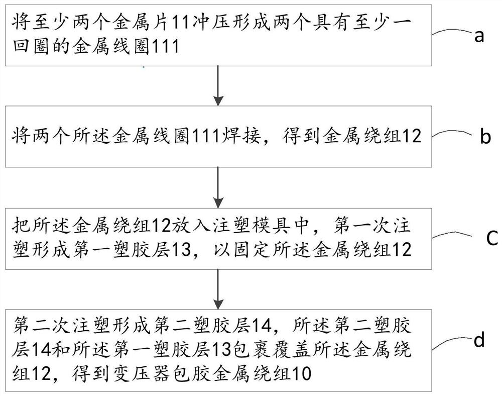
[0002] At present, it is rare to see rubber-coated spiral metal windings used in transformers, because most of the rubber-coated metal products on the market are low-voltage or lower than 380 volt products, and basically most of the current plastic-coated metal products have no temperature. Grade requirements, so it cannot meet the high temperature and high voltage requirements of the transformer
It is also worth mentioning that when encapsulating metal products through the existing metal encapsulation method, it is difficult for the metal product to be positioned in the injection mold, especially for thin metal sheets. Uncontrollable, resulting in poor quality rubber-covered metal products, and the possibility of short circuits during injection molding due to metal displacement
Therefore, the performance of the rubber-coated metal products obtained by the existing rubber-coating method is not good, and the scope of use is relatively limited, so it cannot be applied to transformers
In other words, through the existing metal encapsulation method, it is difficult to ensure that the obtained encapsulating metal products can withstand high temperature and high pressure, and it is also difficult to meet the safety requirements of UL60950

Method used


Image

  • Transformer rubber-coated metal winding and rubber coating method thereof
  • Transformer rubber-coated metal winding and rubber coating method thereof
  • Transformer rubber-coated metal winding and rubber coating method thereof

Examples


Embodiment Construction

[0028] The following description serves to disclose the present invention to enable those skilled in the art to carry out the present invention. The preferred embodiments described below are only examples, and those skilled in the art can devise other obvious variations. The basic principles of the present invention defined in the following description can be applied to other embodiments, variations, improvements, equivalents and other technical solutions without departing from the spirit and scope of the present invention.

[0029] Those skilled in the art should understand that, in the disclosure of the present invention, the terms "vertical", "transverse", "upper", "lower", "front", "rear", "left", "right", The orientations or positional relationships indicated by "vertical", "horizontal", "top", "bottom", "inner", "outer", etc. are based on the orientation or positional relationship shown in the drawings, which are only for the convenience of describing the present inventi...


PUM

PropertyMeasurementUnit
thicknessaaaaaaaaaa

Abstract

The invention relates to a transformer rubber-coated metal winding and a rubber coating method thereof, a metal coil capable of being stacked and assembled is formed by stamping metal sheets in a planar spiral mode, and the number of turns of the formed metal winding is increased by stacking and welding the metal coil. The transformer rubber-coated metal winding is formed in a mode of carrying outinjection molding and rubber coating on the metal winding for at least two times, so that the problem that the metal winding is difficult to position in a mold is solved, and the problem that an existing rubber-coated metal product is not resistant to high pressure is solved; and due to the fact that the transformer rubber-coated metal winding is provided with the at least two plastic layers in the injection molding mode, the transformer rubber-coated metal winding has good insulation performance, can tolerate high temperature and high pressure and has good safety performance so as to meet the use requirement in a transformer and the safety requirement of UL60950.

Description

technical field [0001] The invention relates to the technical field of metal winding wrapping, in particular to a transformer wrapping metal winding capable of withstanding high voltage and a wrapping method thereof. Background technique [0002] At present, it is rare to see rubber-coated spiral metal windings used in transformers, because most of the rubber-coated metal products on the market are low-voltage or lower than 380 volt products, and basically most of the current plastic-coated metal products have no temperature. Grade requirements, so it cannot meet the high temperature and high voltage requirements of the transformer. It is also worth mentioning that when encapsulating metal products through the existing metal encapsulation method, it is difficult for the metal product to be positioned in the injection mold, especially for thin metal sheets. Uncontrollable, the resulting rubberized metal product is of poor quality, and there is a possibility of short circuits...

Claims


Application Information

Patent Timeline
Patent Type & Authority Applications(China)
IPC IPC(8): H01F41/04H01F41/12H01F27/28H01F27/32
CPCH01F41/04H01F41/12H01F41/125H01F27/2847H01F27/2871H01F27/324
Inventor 于龙章陈树林袁红梅黄显峰
Owner WURTH ELECTRONICSCHONGQING
Why Eureka
Try Eureka