Path division multiple access method based on large-scale MIMO-OTFS
A MIMO-OTFS, access method technology, applied in the field of path division multiple access, can solve the problems of non-negligible errors, sensitive user mobility conditions, waste of spectrum resources, etc., and achieve the effect of low complexity
- Summary
- Abstract
- Description
- Claims
- Application Information
AI Technical Summary
Problems solved by technology
Method used
Image

Examples
Embodiment Construction
[0108] In order to make the object, technical solution and advantages of the present invention more clear, the present invention will be further described in detail below in conjunction with the examples. It should be understood that the specific embodiments described here are only used to explain the present invention, not to limit the present invention.
[0109] Aiming at the problems existing in the prior art, the present invention provides a method for diameter division multiple access based on massive MIMO-OTFS. The present invention will be described in detail below in conjunction with the accompanying drawings.
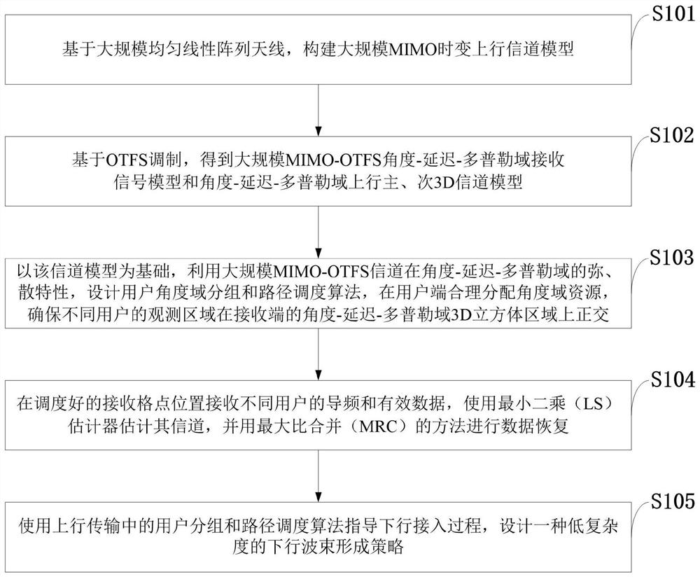
[0110] like figure 1 As shown, the RDMA method provided by the present invention comprises the following steps:
[0111] S101: Construct a massive MIMO time-varying uplink channel model based on a large-scale uniform linear array antenna;
[0112] S102: Based on OTFS modulation, obtain a large-scale MIMO-OTFS angle-delay-Doppler domain receiving signal model ...
PUM
 Abstract
Description
Claims
Application Information
 - Generate Ideas
- Intellectual Property
- Life Sciences
- Materials
- Tech Scout
- Unparalleled Data Quality
- Higher Quality Content
- 60% Fewer Hallucinations
Browse by: Latest US Patents, China's latest patents, Technical Efficacy Thesaurus, Application Domain, Technology Topic, Popular Technical Reports.
© 2025 PatSnap. All rights reserved.Legal|Privacy policy|Modern Slavery Act Transparency Statement|Sitemap|About US| Contact US: help@patsnap.com