Pickup device and cavity wall member for same

A technology of sound pickup equipment and sound cavity, which is applied in the direction of electrical components, sensor parts, microphone mouth/microphone accessories, etc., can solve the problems of limited application scenarios, achieve the effect of compensating loss and increasing thickness

Pending Publication Date: 2020-12-15
HANGZHOU HIKVISION DIGITAL TECH
View PDF12 Cites 2 Cited by
  • Summary
  • Abstract
  • Description
  • Claims
  • Application Information

AI Technical Summary

Problems solved by technology

However, the application scenarios of this method are relatively limited. It must be applied to the on-board microphone or when there is gr

Method used


Image

  • Pickup device and cavity wall member for same
  • Pickup device and cavity wall member for same
  • Pickup device and cavity wall member for same

Examples


Embodiment Construction

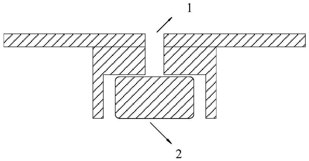
[0035] In order to have a clearer understanding of the technical features, purposes and effects of the invention, the specific implementation manners of the present invention will now be described with reference to the accompanying drawings, in which the same reference numerals represent the same parts.

[0036] In this article, "schematic" means "serving as an example, example or illustration", and any illustration or implementation described as "schematic" should not be interpreted as a more preferred or more advantageous Technical solutions.

[0037] In order to make the drawings concise, the figures in each figure only schematically show the relevant parts of the present invention, and do not represent the actual structure of the product. In addition, to make the drawings concise and easy to understand, in some drawings, only one of the components having the same structure or function is schematically shown, or only one of them is marked.

[0038] In order to solve the el...


PUM


Abstract

The present invention discloses a pickup device and a cavity wall member for the pickup device, comprising: a housing having a pickup hole on a surface thereof; a microphone, wherein the microphone isarranged in the shell; a tunnel sound cavity which is formed in the shell, the microphone is formed in the shell, the tunnel sound cavity is formed in the shell and isolated between the pickup hole and the microphone, the pickup hole and the microphone are both communicated with the tunnel sound cavity, and sound waves entering the shell through the pickup hole are collected by the microphone through the tunnel sound cavity. According to the pickup device and the cavity wall component for the pickup device, the tunnel sound cavity is formed between the pickup hole and the microphone to increase the distance between the pickup hole and the microphone so as to achieve the effect of electrostatic isolation; and the loss of the sound intensity caused by the distance is compensated through theoscillation effect of the sound wave in the tunnel sound cavity.

Description

technical field [0001] The invention relates to the technical field of sound pickup equipment, in particular to a sound pickup equipment and a cavity wall member used for the sound pickup equipment. Background technique [0002] In the recording device, because the distance between the recording hole of the microphone and the microphone is too close, static interference is likely to be generated, which will cause damage to the microphone or internal circuits and affect the use effect. At present, the main ways to solve the problem of electrostatic interference in the recording hole are hardware circuit protection and structural shrinkage design. [0003] For some chips with weak antistatic ability, when the product thickness is thin and the structure shrinkage cannot meet the electrostatic insulation requirements, the hardware circuit protection alone cannot solve the electrostatic interference problem; although the structure shrinkage can better solve the electrostatic inte...

Claims


Application Information

Patent Timeline
IPC IPC(8): H04R1/08
CPCH04R1/083
Inventor 胡进军阚江南
Owner HANGZHOU HIKVISION DIGITAL TECH
Why Eureka
Try Eureka