Knob device

A technology of knobs and wire wheels, which is applied to clothing, fastening objects, shoes, etc., can solve the problems that counterclockwise rotation cannot be prevented at any time, the wire wheel cannot rotate freely, and the degree of tightness is difficult to adjust, etc., to achieve sound Crisp and pleasing to the ear, improving the degree of recognition, and the effect of reasonable stress state

Pending Publication Date: 2020-12-18
李付德
View PDF1 Cites 2 Cited by
  • Summary
  • Abstract
  • Description
  • Claims
  • Application Information

AI Technical Summary

Problems solved by technology

[0002] The traditional way of tying shoelaces usually requires both hands to operate at the same time. The speed is relatively slow, and it takes a long time to bend down and squat down, which increases the discomfort of the human body, especially in the cold winter, when the clothes are thicker. , tying shoelaces has become a very strenuous thing, and the usual way of tying shoelaces is not easy to adjust the degree of tightness, which makes the instep feel bad, either loose or tight, and it needs to be adjusted to a suitable degree of tightness It takes a lot of effort, but it is not easy for the elderly and children. The shoelaces are easy to loose, and the loose shoelaces may be stepped on by the other foot when walking, causing the body to lose balance and cause safety accidents;
[0003] In view of the above technical problems, it is known that a prior art patent can overcome the above technical problems, which discloses a lacing device and its control components (application number: CN201820684579.1, application date: 20180509, publication date: 20190122), Including: a control assembly of a lacing device, characterized in that it includes: "a knob with circumferential teeth and first end teeth, the knob is provided with a fixing hole; a pawl wheel housing with a pawl installed inside, The ratchet wheel bin is partly arranged in the knob; there is a winding wheel with a convex rotating shaft and a second end face tooth, and the winding wheel is sleeved in the ratchet wheel bin, and the convex rotating shaft Pass through the ratchet wheel chamber and insert into the positioning hole of the knob, the knob drives the reel to rotate... the rope threading part is set on the upper of the shoe, and the control component is set on the upper of the shoe On the side or on the shoe tongue", use the cap to drive the reel to rotate, and adjust the tightness of the upper by tightening the winding to achieve fast tying of shoelaces, but this kind of shoelace device that uses the cap to drive the reel to rotate It is necessary to press or pull up the screw cap to be able to rotate counterclockwise, and it cannot prevent it from rotating counterclockwise at any time, and the wire wheel in the existing screw cap drives the reel to rotate. It can achieve the situation of free rotation, which makes it impossible for the user to adjust the shoelace more easily and achieve the purpose of loosening the shoelace

Method used


Image

  • Knob device
  • Knob device
  • Knob device

Examples


specific Embodiment approach

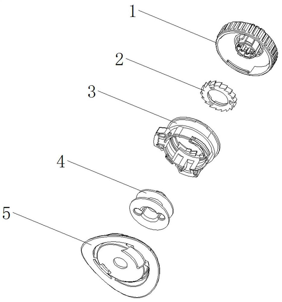
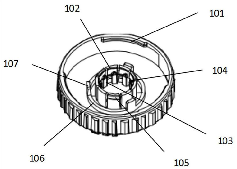
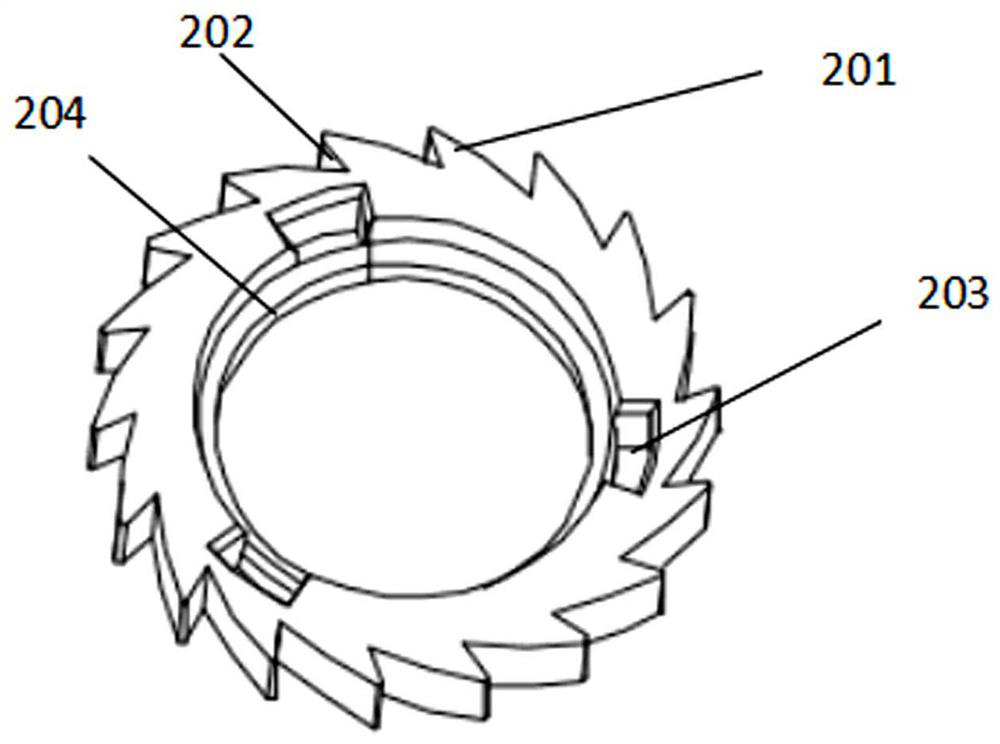
[0057] Tighten the shoelaces, press the knob 1 assembly slightly toward the base 5, and when you hear a "click", the knob 1 is in a combined state with the ratchet wheel compartment 3 and the wire wheel 4. During this process, the wire wheel 4 The protruding structure 403 is pressed into the concave structure 104 in the knob 1, the central circular bone structure 102 of the knob 1 is combined with the annular bone structure 401 of the wire wheel 4, and the load on the circular bone structure 102 Muscle 1 103 intersects with load 2 402 on the wire wheel, and the locking teeth 201 on the ratchet ring 2 and the ratchet teeth 302 on the ratchet wheel bin 3 are also in meshing state. Turn the knob clockwise, and the ratchet ring 2 The latch tooth 201 on the ratchet wheel bin 3 can cross the ratchet tooth 302 on the ratchet wheel bin 3, but in the ratchet wheel bin 3, there is always a ratchet tooth end surface position 303 of the ratchet tooth 302 facing the ratchet ring 2. The pos...


PUM


Abstract

The invention provides a knob device. The knob device comprises a knob, a wheel bin, a line wheel, a base and a shoelace, wherein the base is sewn on the side surface of an upper or a tongue; a buttonposition is arranged on the inner circumferential edge of the knob; a plurality of square holes are formed in the circumferential edge of the wheel bin; a plurality of rope penetrating holes I are formed in the lower part of the outer circle of the wheel bin; a line groove is formed in the middle of the line wheel; a plurality of rope penetrating holes are formed in the line wheel; a counter borestructure is arranged in the center of the bottom of the line wheel; the knob device further comprises a gear ring; clamping teeth capable of preventing the gear ring from rotating are arranged on the gear ring; and a blocking mechanism corresponding to the clamping teeth arranged on the gear ring is arranged on the wheel bin. The knob device is better in reliability; when a pawl arm on the wheelbin is stressed reversely, the pawl arm deforms towards the centrifugal direction, pawl teeth and ratchets on the pawl arm are tightly attached together, circumferential teeth and ratchet teeth on the pawl arm are tightly attached together, and the stress states of the pawl arm, the ratchets, the circumferential teeth and the ratchet teeth are very ideal, so that the structure is higher in reliability when stressed reversely.

Description

technical field [0001] The invention relates to the technical field of rope fastening and loosening, in particular to a knob device using a rope or a steel wire rope. Background technique [0002] The traditional way of tying shoelaces usually requires both hands to operate at the same time. The speed is relatively slow, and it takes a long time to bend down and squat down, which increases the discomfort of the human body, especially in the cold winter, when the clothes are thicker. , tying shoelaces has become a very strenuous thing, and the usual way of tying shoelaces is not easy to adjust the degree of tightness, which makes the instep feel bad, either loose or tight, and it needs to be adjusted to a suitable degree of tightness It takes a lot of effort, but it is not easy for the elderly and children. The shoelaces are easy to loose, and the loose shoelaces may be stepped on by the other foot when walking, causing the body to lose balance and cause safety accidents; ...

Claims


Application Information

Patent Timeline
Patent Type & Authority Applications(China)
IPC IPC(8): A43C11/16A43C11/00
CPCA43C11/16A43C11/00A43C11/165A43C11/20
Inventor 李付德
Owner 李付德
Why Eureka
Try Eureka