Supercharge Your Innovation With Domain-Expert AI Agents!

Novel rubber cutting machine for rubber preparation

A rubber cutting machine and rubber technology, applied in the field of rubber, can solve the problems of laborious replacement, only complete replacement, and high cost, and achieve the effects of ensuring cutting quality, speeding up cutting, and increasing flexibility in use

Inactive Publication Date: 2020-12-18
泉州市良创信息科技有限公司
View PDF6 Cites 0 Cited by
  • Summary
  • Abstract
  • Description
  • Claims
  • Application Information

AI Technical Summary

Problems solved by technology

[0003] The existing technology has the following problems: the blade must be used to cut the rubber, and the blade also needs to be maintained or replaced after a long period of use. The existing blade is fixedly connected to the telescopic rod of the upper hydraulic cylinder, so that only Whole replacement, this replacement method is costly and laborious when replacing

Method used


Image

  • Novel rubber cutting machine for rubber preparation
  • Novel rubber cutting machine for rubber preparation
  • Novel rubber cutting machine for rubber preparation

Examples


Embodiment 1

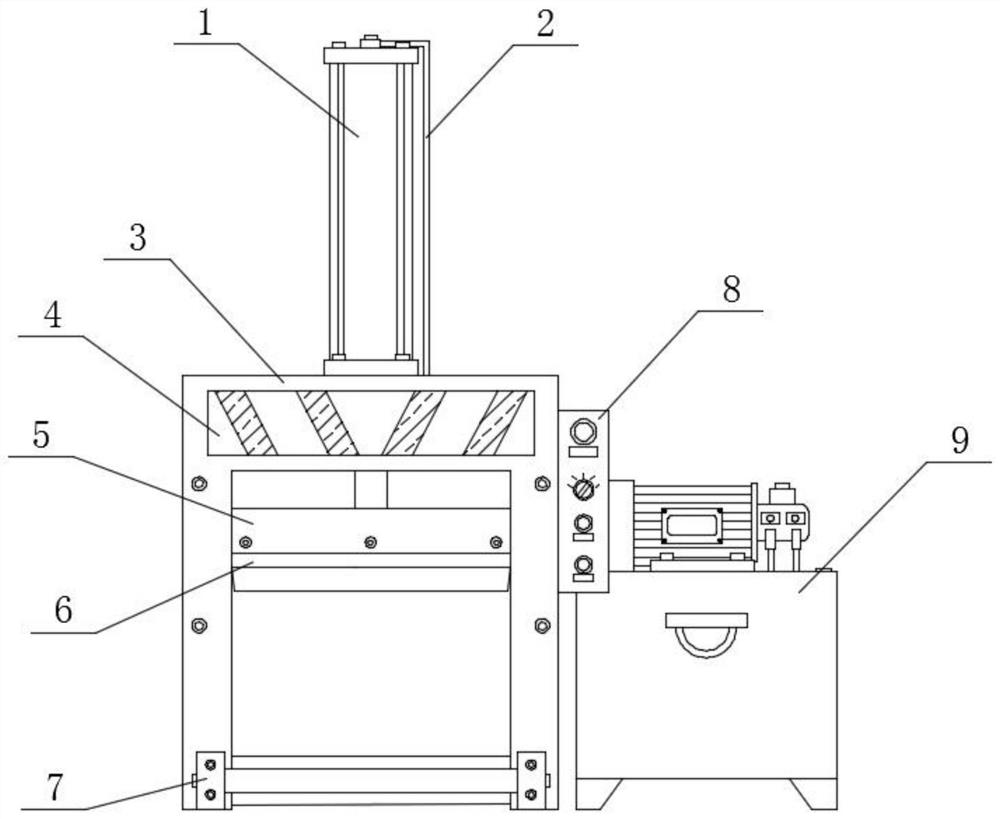
[0031] Such as Figure 1-4 As shown, a new type of rubber cutting machine for rubber preparation includes a cutting table 3 and a hydraulic cylinder 1. The top end of the cutting table 3 is connected with a hydraulic cylinder 1. The hydraulic cylinder 1 can be connected with the hydraulic oil pump 9 through the oil pipe 2. The bottom end face of the oil cylinder 1 is connected with a telescopic rod inside the front end face of the cutting table 3, and the oil pipe 2 is connected to the right side of the top end face of the hydraulic cylinder 1. The inner surface of the oil pipe 2 is hollow, and the telescopic rod can drive the fixed frame 5 Carry out up and down movement to realize the cutting function. The lower part of the oil pipe 2 is provided with a reflective sticker 4 at the position above the front end of the cutting table 3. The reflective sticker 4 is reflective and arranged symmetrically. The lower part of the reflective sticker 4 is located on the cutting table. Th...

Embodiment 2

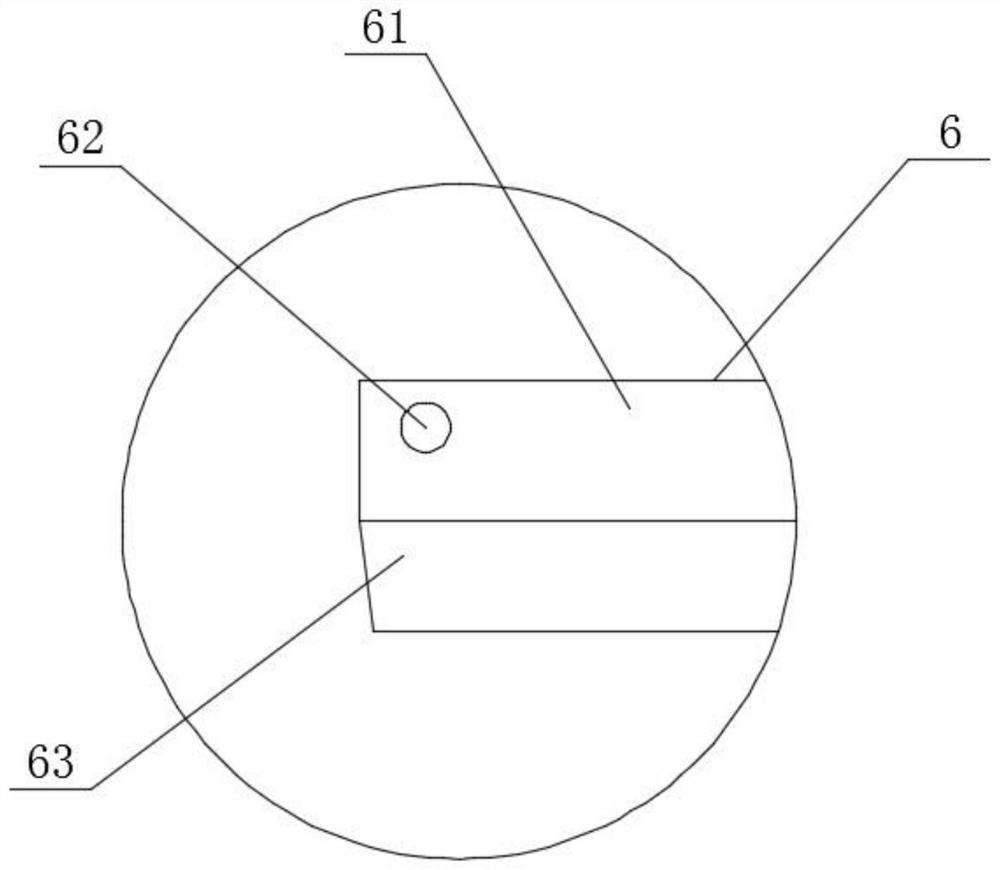
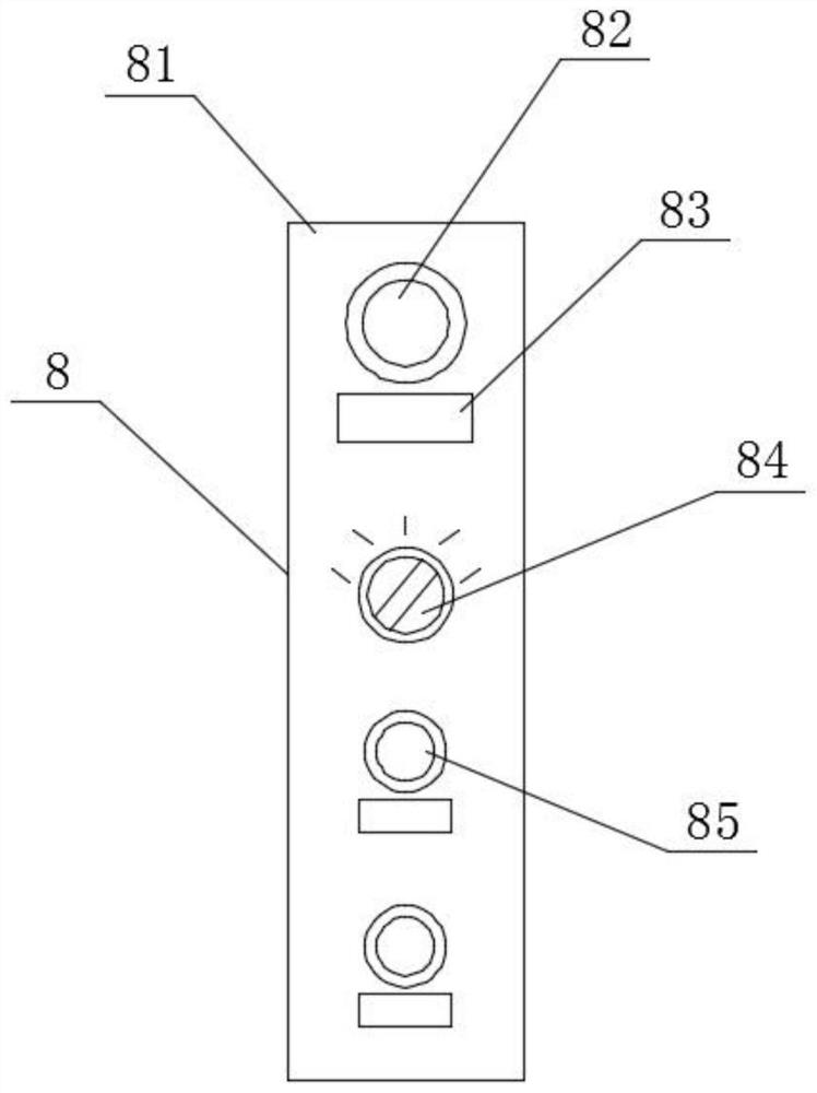
[0035] Such as Figure 1-7 As shown, a new rubber cutting machine for rubber preparation includes a cutting table 3 and a hydraulic cylinder 1. The top end surface of the cutting table 3 is connected to the hydraulic cylinder 1, and the right side of the top end surface of the hydraulic cylinder 1 is connected to the oil pipe 2. The oil pipe 2 The lower part is provided with a reflective sticker 4 at the upper position of the front end face of the cutting table 3, and the lower part of the reflective sticker 4 is provided with a fixing frame 5 inside the front end face of the cutting table 3, and the bottom end face of the fixing frame 5 is connected by bolts. The blade 6 is disassembled, and a roller table 7 is arranged below the front end face of the cutting table 3 under the dismantling blade 6, and an operation panel 8 is arranged above the roller table 7 above the right end face of the cutting table 3 , the rear of the operation panel 8 is provided with a hydraulic oil pu...


PUM


Abstract

The invention provides a novel rubber cutting machine for rubber preparation. The novel rubber cutting machine comprises a cutting table and a hydraulic oil cylinder, the end face of the top end of the cutting table is connected with the hydraulic oil cylinder, the right side of the end face of the top end of the hydraulic oil cylinder is connected with an oil pipe, and a reflective sticker is arranged at the position, on the upper portion of the end face of the front end of the cutting table, below the oil pipe; and a fixed blade is arranged at the position, on the inner side of the end faceof the front end of the cutting table, below the reflective sticker, and the end face of the bottom end of the fixed blade is connected with a detachable blade through a bolt. The end faces of the bottom ends of the cutting blades are sharpened, so that external rubber is effectively cut; in the using process, the blades are frequently replaced, the cutting speed is effectively increased, meanwhile, the cutting quality is guaranteed, the overall practicability is improved through the detachable arrangement of the detachable blade, more labor is saved and environmental friendliness is achievedin the subsequent replacement process, and the trouble problem caused by the fact that existing blades can only be integrally replaced is avoided through the arrangement of the detachable blade.

Description

technical field [0001] The invention relates to the field of rubber, in particular to a novel rubber cutting machine for rubber preparation. Background technique [0002] Rubber refers to a highly elastic polymer material with reversible deformation. It is elastic at room temperature and can produce large deformation under a small external force. After removing the external force, it can return to its original shape. Rubber is a completely amorphous polymer. Its glass The transformation temperature is low, and the molecular weight is often very large. In the current rubber preparation, it is necessary to use a special rubber cutting machine to cut the rubber into a specified size and shape. [0003] The existing technology has the following problems: the blade must be used to cut the rubber, and the blade needs to be maintained or replaced after a long period of use. The existing blade is fixedly connected to the telescopic rod of the upper hydraulic cylinder, so that only ...

Claims


Application Information

Patent Timeline
IPC IPC(8): B26D7/26B26D7/18
CPCB26D7/18B26D7/2614
Inventor 苏少辉何锋锋
Owner 泉州市良创信息科技有限公司
Features
  • R&D
  • Intellectual Property
  • Life Sciences
  • Materials
  • Tech Scout
  • Unparalleled Data Quality
  • Higher Quality Content
  • 60% Fewer Hallucinations
Learn More