
A car air conditioner vent

A technology for automotive air conditioners and air outlets, which is applied to vehicle components, air handling equipment, heating/cooling equipment, etc. It can solve the problems of different air intakes, affecting the feeling of blowing, and different wind speeds and air volumes at the air outlets. Accurate angle and good wind guiding effect

Active Publication Date: 2021-02-02
NINGBO JOYSONQUIN AUTOMOTIVE SYST HLDG CO LTD
View PDF1 Cites 0 Cited by
  • Summary
  • Abstract
  • Description
  • Claims
  • Application Information

AI Technical Summary

Problems solved by technology

[0004] The applicant's previous application (publication number: CN109823143A) discloses an air outlet device, an air conditioning system and a vehicle, including a first channel, a second channel, and a shielding part. The inlet of the first channel and the inlet of the second channel enter the first channel and the second channel, and then flow out and interact with each other through the outlet of the first channel and the outlet of the second channel, see the previous application Figure 3 to Figure 6 As shown, it blocks the entrance of the first passage and the entrance of the second passage through the shielding part, so that the air intake areas of the first passage and the second passage are different, and the air intake volumes entering the first passage and the second passage are different, realizing The adjustment of the blowing angle, however, with this structure, when the air enters, the air intake area of ​​the first channel and the second channel are different due to the existence of the shielding part, resulting in a difference in the air intake volume of the first channel and the second channel. As a result, the wind speed and air volume of the air outlet are different, which affects the feeling of blowing

Method used


Image

  • A car air conditioner vent
  • A car air conditioner vent
  • A car air conditioner vent

Examples


Embodiment Construction

[0031] The present invention is further explained in conjunction with the accompanying drawings.

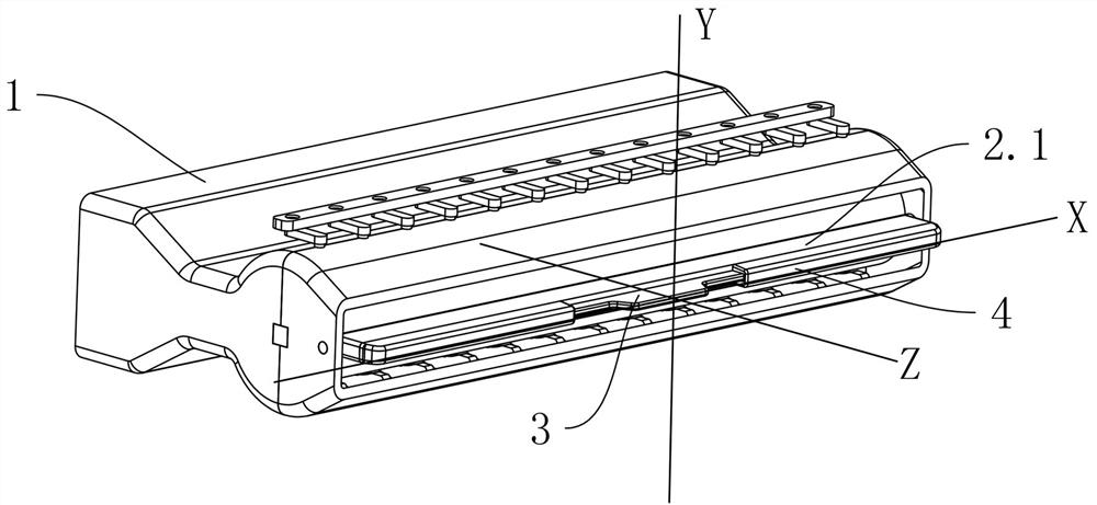
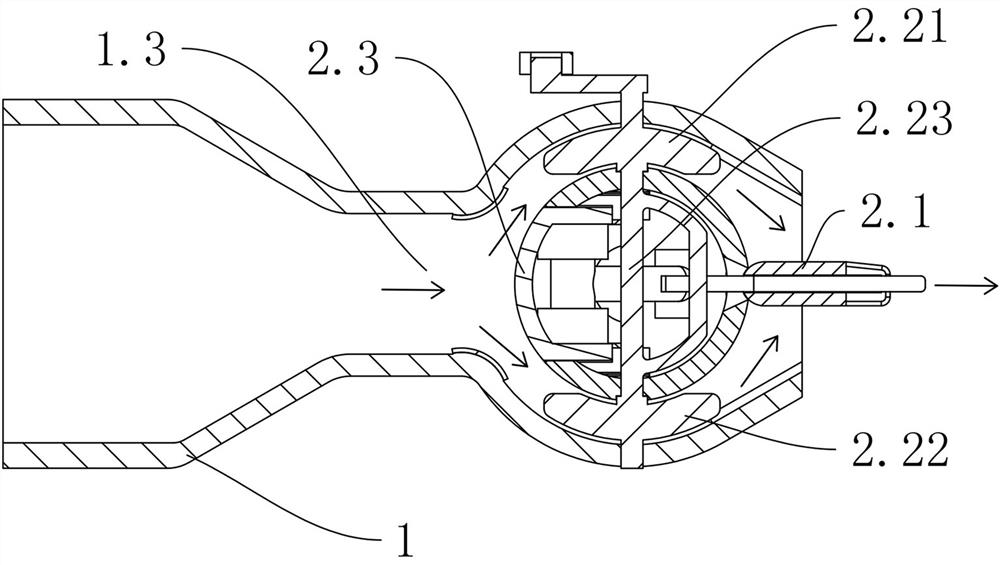
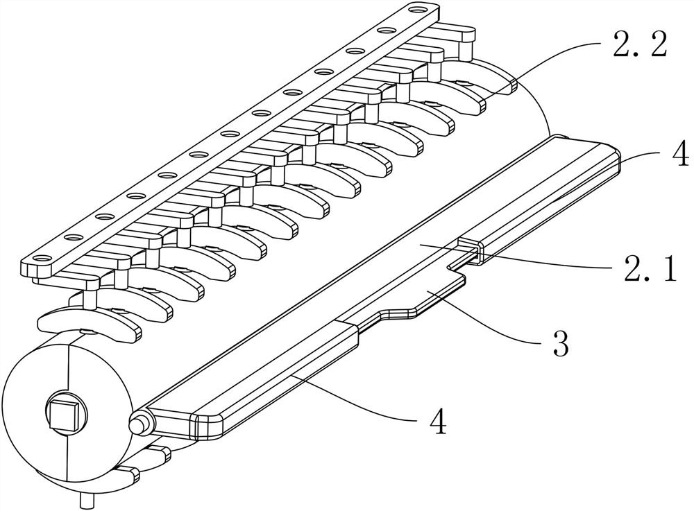
[0032] see Figure 1 to Figure 10 The air outlet of an automobile air conditioner shown includes a housing 1 and an air guide mechanism 2. The housing 1 also has an air inlet channel 1.3 and an air outlet channel in turn. The housing 1 is fixed with a cylindrical Shaped flow divider 1.4, located in the air outlet channel, the flow divider 1.4 protrudes upwards and forms the upper air duct 1.1 between the casing 1, the flow divider 1.4 protrudes downwards and The lower air passage 1.2 is formed between the casing 1, the entrance of the upper air passage 1.1 and the entrance of the lower air passage 1.2 communicate with the opening of the air inlet passage 1.3 respectively, and the upper air passage 1.1 has an upper bend part so that the outlet of the upper air passage 1.1 is configured to output the first airflow, and the lower air passage 1.2 has a lower bent part so that the ou...


PUM


Abstract

The invention discloses an air outlet of an automobile air conditioner, which comprises a housing and an air guiding mechanism. The housing is provided with an air inlet passage and an air outlet passage successively. The air outlet passage includes an upper air passage and a lower air passage. The upper air passage is covered by Configured to output the first airflow, the lower air duct is configured to output the second airflow intersecting with the first airflow, the air guide mechanism includes a single main blade arranged at the opening of the housing and arranged at the The damper in the air outlet channel; the main blade is provided with a damper operating member connected with the damper transmission, when the main blade rotates around the X axis, the direction of the first airflow and the second airflow of the main blade The direction of the windshield is guided so as to realize the adjustment of the longitudinal air guide, and the damper operating part drives the damper to cooperate with the housing so as to adjust the air volume of the air inlet channel. The air outlet of an automobile air conditioner provided by the invention has simple structure and good blowing effect.

Description

technical field [0001] The invention relates to the technical field of automobile accessories, in particular to an air outlet of an automobile air conditioner. Background technique [0002] The air outlet of the car air conditioner is one of the necessary parts of the car. In order to meet the temperature requirements of drivers of different heights, different shapes, and different habits, the air outlet of the car air conditioner on the market is generally used to control the main blade, secondary blade, damper and other components. To achieve wind direction adjustment. [0003] At present, in the automotive interior industry, the invisible air outlet of the air conditioner is forming a trend, and the corresponding shell shapes are becoming more and more diverse. A new type of high-width ratio narrow and long shell is characterized by two or more fixed diverters. Composition, based on the Coanda effect of the fluid, deflects the wind direction by controlling the flow of ea...

Claims


Application Information

Patent Timeline
Patent Type & Authority Patents(China)
IPC IPC(8): B60H1/34
CPCB60H1/3414
Inventor 龚柠涛王泽星张生锋
Owner NINGBO JOYSONQUIN AUTOMOTIVE SYST HLDG CO LTD
Learn More