
EGR gas inlet rail

A track and air intake technology, applied in the direction of exhaust gas recirculation, engine components, machines/engines, etc., can solve problems that affect engine life and performance, uneven intake of engine cylinders, uneven engine air pressure, etc., to avoid airflow Straight into the engine cylinder, wide range of airflow adjustment, uniform gas effect

Inactive Publication Date: 2018-10-12
台州滨海吉利发动机有限公司 +1
View PDF6 Cites 0 Cited by
  • Summary
  • Abstract
  • Description
  • Claims
  • Application Information

AI Technical Summary

Problems solved by technology

If this structure is applied to a three-cylinder engine, the number of air outlets is odd, so that the air outlet located in the center bears a relatively large air pressure, resulting in uneven air intake in the engine cylinders
And because the intake manifold is connected with the EGR exhaust gas, when the EGR control valve is opened, the air pressure in the intake manifold will change, and the intake manifold itself is distributed through a single air chamber and the size of the outlet is fixed, so in After the additional air pressure is added, it is easy to change the original air distribution balance, resulting in uneven air pressure in each engine, and then easily causing a certain cylinder engine to misfire, or a certain cylinder to knock, which will affect the life and performance of the engine.

Method used


Image

  • EGR gas inlet rail
  • EGR gas inlet rail

Examples


Embodiment 1

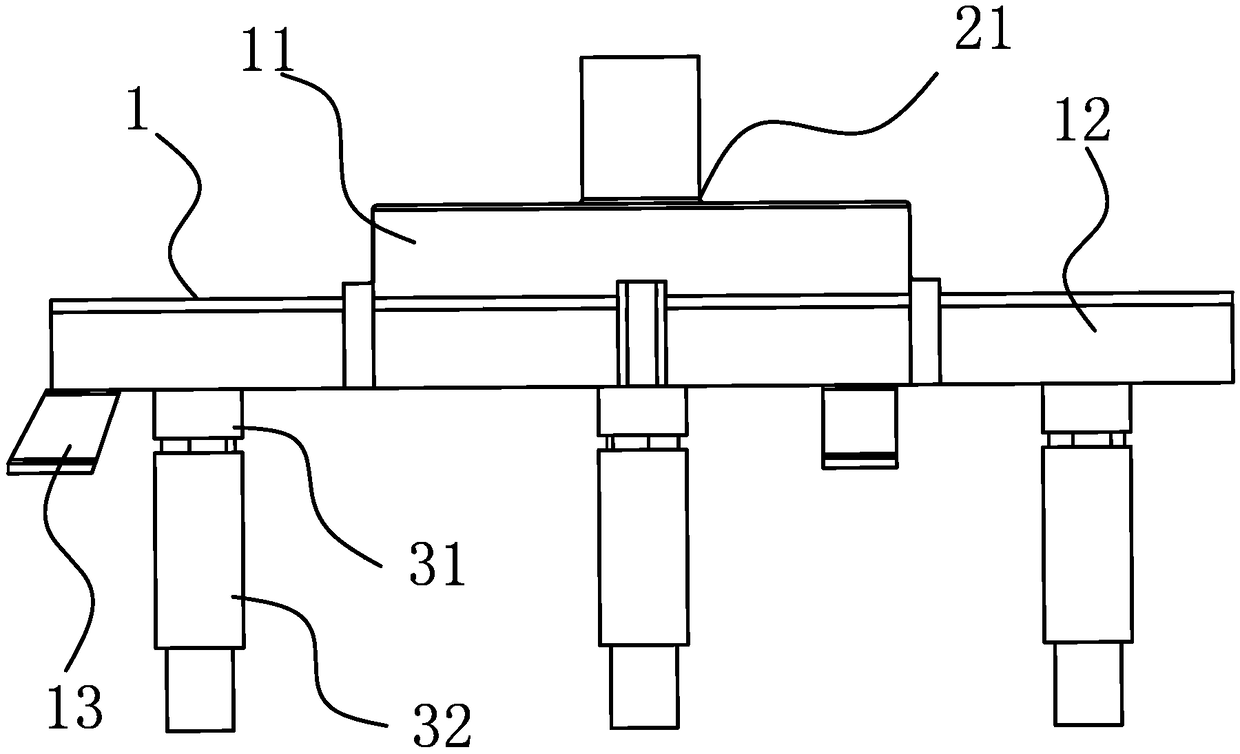
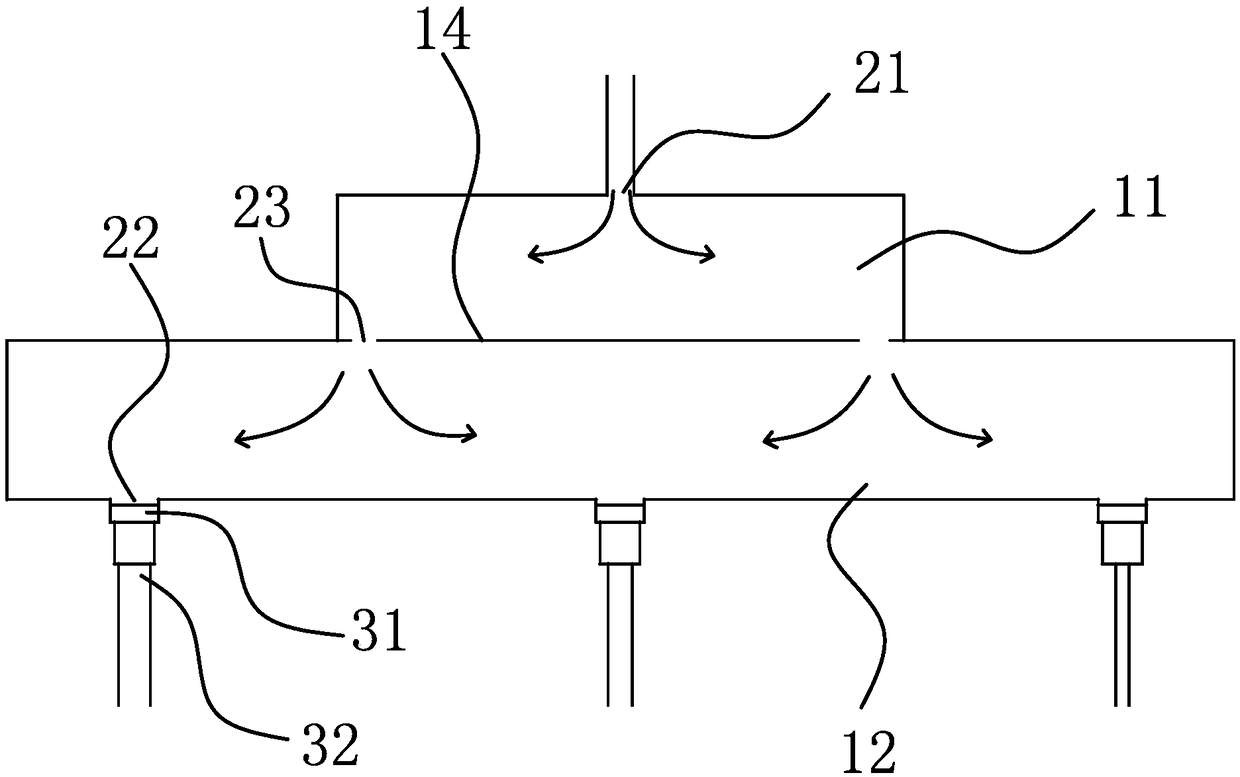
[0027] Such as figure 1 and figure 2 As shown, an EGR intake rail includes a housing 1 , and an upper air chamber 11 and a lower air chamber 12 are arranged inside the housing 1 . The top of the upper air chamber 11 is provided with an air inlet 21 for connecting the EGR air duct, the upper air chamber 11 and the lower air chamber 12 are separated by a partition 14, and an air guide port 23 for communication is provided on the partition 14. An air outlet 22 is provided at the bottom of the lower air chamber 12, and the air outlet 22 is used to introduce the gas in the lower air chamber 12 into the engine cylinder. The inner top wall of dividing plate 14 and upper floor air chamber 11 is parallel to each other, and air inlet 21 is positioned on the inner top wall of upper floor air chamber 11, and the inner bottom wall of dividing plate 14 and lower floor air chamber 12 is parallel mutually, upper floor air chamber 11 and The inside of the lower floor air chamber 12 is a squ...

Embodiment 2

[0033] The difference between the second embodiment and the first embodiment lies in the detachable connection between the intake branch pipe 32 and the movable block 31. The overlapping part is kept relatively fixed by the clamp. The other end of the sebific tube is fixed on the engine cylinder head and communicates with the air intake of the engine cylinder head.


PUM


Abstract

The invention provides an EGR gas inlet rail, and belongs to the technical field of automobile accessories. The EGR gas inlet rail solves the technical problem that in the prior art, the gas amount ofeach air cylinder is unequal after waste gas enters the air cylinders. The EGR gas inlet rail comprises a shell, wherein an upper gas chamber and a lower gas chamber are arranged in the shell, the shell is provided with a gas inlet and gas outlets, the air inlet is used for enabling the upper gas chamber to communicate with an EGR gas guide pipe, and the air outlets are used for being connected with the air cylinders of an engine in a one-to-one correspondence mode; and the gas outlets communicate with the lower gas chamber, gas guide holes used for enabling the upper gas chamber to communicate with the lower gas chamber are formed between the upper gas chamber and the lower gas chamber, the gas inlet is formed between the two adjacent gas guide holes, and the gas guide hole is formed between every two adjacent gas outlets. According to the EGR gas inlet rail, the gas in the gas outlets can be matched with incoming gas in a gas inlet pipe, so that the gas in each air cylinder of the engine is uniform, and the operation of the air cylinders is stable.

Description

technical field [0001] The invention belongs to the field of auto parts and relates to an EGR intake rail. Background technique [0002] Gasoline engine is the power device of the car. It generates the power to propel the car forward by burning the mixture of oil and fresh air. Due to the different working conditions of the engine cylinders, some oil-air mixture is discharged before being fully combusted. In order to meet the requirements of the current emission regulations, the EGR technology of exhaust gas recirculation has been widely used. It separates the oil and gas in the exhaust pipe of the gasoline engine and sends it back to the engine cylinder for re-combustion, so as to reduce the fuel consumption of the car and the exhaust gas to reach Environmental requirements. [0003] my country's patent application literature (notification number: CN203383943U; announcement date: 2014.1.8) discloses a light engine intake pipe, including an intake manifold, and an EGR exhau...

Claims


Application Information

Patent Timeline
IPC IPC(8): F02M26/20
CPCF02M26/20
Inventor 佟铁刚陈旗奇姚丽君管奇贤李强张贵强赵福成王瑞平
Owner 台州滨海吉利发动机有限公司
Learn More