Automobile rear bumper and automobile

A technology for rear protection and protective bars, which is applied in the direction of bumpers, vehicle parts, spare tires, etc., can solve problems such as installation difficulties, manual corrections, and damage to casings due to force, so as to be easy to popularize and practical, reduce production requirements, and avoid The effect of force damage

Pending Publication Date: 2020-12-18
WINBO DONGJIAN AUTOMOTIVE TECHNOLOGY CO LTD
View PDF0 Cites 2 Cited by
  • Summary
  • Abstract
  • Description
  • Claims
  • Application Information

AI Technical Summary

Problems solved by technology

This method has extremely high requirements on the verticality of the shaft and the pump handle, and it is difficult to guarantee the accuracy of production and processing. It often requires a lot of manual corrections, inter-matching inspections, etc., which not only causes waste of resources, but also may eventually lead to failure of the product to be installed. Or installation is difficult, causing the product to be scrapped
On the other hand, although the casing can be adjusted at a certain angle, thereby realizing the height adjustment of the spare tire rack, but because the rotating shaft is cylindrical, the casing is damaged by force during adjustment, resulting in structural failure

Method used


Image

  • Automobile rear bumper and automobile
  • Automobile rear bumper and automobile
  • Automobile rear bumper and automobile

Examples


Embodiment Construction

[0023] The specific implementation manners of the present invention will be further described in detail below in conjunction with the accompanying drawings and embodiments. The following examples are used to illustrate the present invention, but are not intended to limit the scope of the present invention.

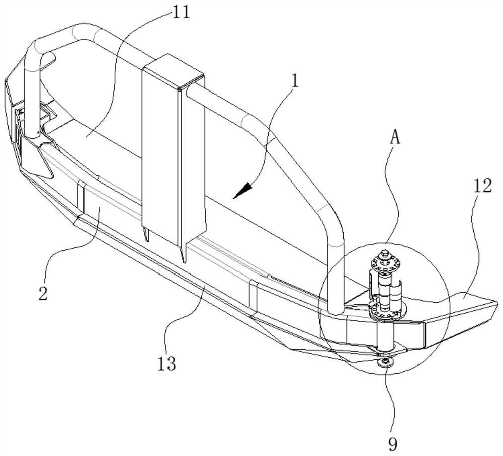
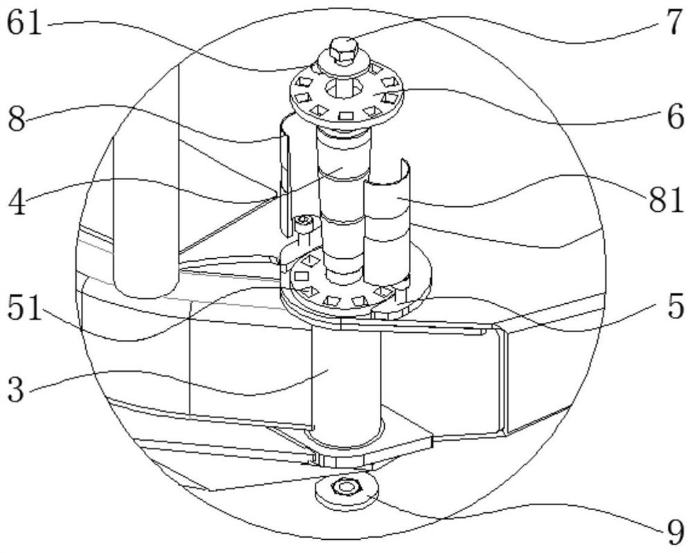
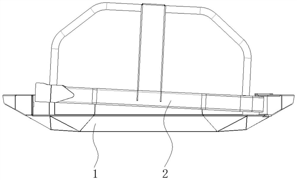
[0024] Such as Figure 1-2 As shown, a car rear bumper in a preferred embodiment of the embodiment of the present invention includes a bumper main body 1 installed at the rear of the car, a spare tire frame 2, a shaft sleeve 3 and a frustum-shaped rotating shaft 4, and the rotating shaft 4 can swing It is arranged at one end of the main body 1 of the protective bar, the bushing 3 is fixed on one end of the spare tire frame 2, and is rotatably sleeved on the rotating shaft 4, and the other end of the spare tire frame 2 can be It is detachably connected to the main body 1 of the protective bar, and is connected by a locking mechanism. This is the prior art and will not be r...


PUM


Abstract

The invention relates to the technical field of automobiles, and discloses an automobile rear bumper and an automobile. The automobile rear bumper comprises a bumper body installed at the tail of theautomobile, a spare wheel carrier, a shaft sleeve and a circular-truncated-cone-shaped rotating shaft; the rotating shaft is arranged at one end of the bumper body in a swinging mode, and the shaft sleeve is fixed at one end of the spare wheel carrier; the spare wheel carrier is arranged on the rotating shaft in a rotating and sleeving mode; and the other end of the spare wheel carrier is detachably connected with the bumper body. According to the automobile rear bumper and the automobile, the circular-truncated-cone-shaped rotating shaft is arranged, and the rotating shaft is arranged at oneend of the bumper body in a swinging mode; meanwhile, the shaft sleeve is arranged at one end of the spare wheel carrier, and the rotating shaft is sleeved with the shaft sleeve so that the lower endof the shaft sleeve can swing left and right around the upper end of the spare wheel carrier when the other end of the spare wheel carrier ascends or descends; free adjustment of the angle of the spare wheel carrier is achieved, damage to the shaft sleeve due to stress during adjustment is avoided, and structural reliability is guaranteed; and vertical precision is not required, production requirements are reduced, and popularization and application are easy.

Description

technical field [0001] The invention relates to the technical field of automobiles, in particular to an automobile rear protection bar and an automobile. Background technique [0002] At present, some models can be equipped with spare tires on their vehicle bodies due to needs, and the installation methods of spare tires are various. One end welding sleeve pipe 300, then sleeve pipe 300 is socketed on the cylindrical rotating shaft 200 and realizes the rotation of spare tire carrier 2 (as Figure 6 ). This method has extremely high requirements on the verticality of the shaft and the pump handle, and it is difficult to guarantee the accuracy of production and processing. It often requires a lot of manual corrections, inter-matching inspections, etc., which not only causes waste of resources, but also may eventually lead to failure of the product to be installed. Or installation is difficult, causing the product to be scrapped. On the other hand, although the sleeve can be ...

Claims


Application Information

Patent Timeline
Patent Type & Authority Applications(China)
IPC IPC(8): B60R19/48B60R19/24B62D43/00
CPCB60R19/24B60R19/48B62D43/00
Inventor 徐汝强陈天权
Owner WINBO DONGJIAN AUTOMOTIVE TECHNOLOGY CO LTD
Why Eureka
Try Eureka