Side blowing device capable of controlling temperature sectionally

A segmented temperature control and side blowing technology, which is applied in textiles and papermaking, fiber processing, filament/thread forming, etc., can solve problems such as long cooling length, unreachable product indicators, and abnormal fiber process, etc., to achieve cooling good effect

Inactive Publication Date: 2020-12-18
DALIAN HUAYANG NEW MATERIALS TECH CO LTD
View PDF13 Cites 1 Cited by
  • Summary
  • Abstract
  • Description
  • Claims
  • Application Information

AI Technical Summary

Problems solved by technology

[0002] The side blowing device is one of the important equipment of the spunbonded nonwoven production line. After the fibers are melted and extruded at high temperature, the fibers are drawn after cooling to improve their orientation and strength and obtain fibers with sufficient strength; at this stage The side blowing device of the company adopts the overall temperature control. This structure can meet the general fiber cooling requirements. However, in the production of some fibers, such as coarse denier polypropylene, due to the long cooling length of the fiber, the overall temperature control The side blowing device cannot satisfy the spinning cooling of the fiber, resulting in the failure of the next step of the fiber process or the failure of the product index to meet the standard

Method used


Image

  • Side blowing device capable of controlling temperature sectionally
  • Side blowing device capable of controlling temperature sectionally
  • Side blowing device capable of controlling temperature sectionally

Examples


Embodiment Construction

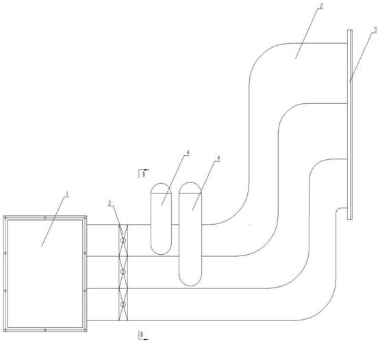
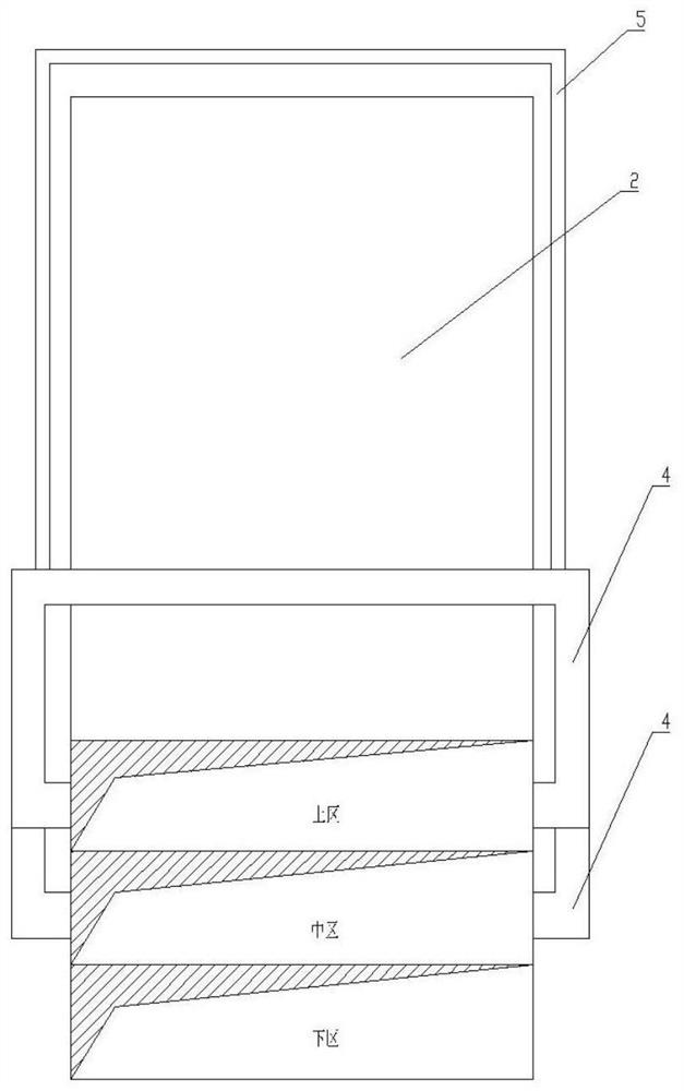
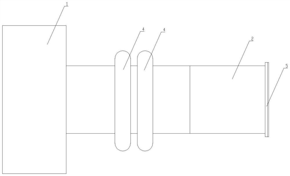
[0020] exist Figure 1 to Figure 3 In the schematic diagram of the device of the present invention shown, one side of the static pressure box 1 has a hole, and the hole is connected to the inlet end of the side blowing flow channel 2 through a flange, and the air-conditioning air is sent into the air after being stabilized by the static pressure box 1. The side blowing channel 2 ensures the stability of the wind pressure. The interior of the air flow channel 2 is divided into the upper area 2.1, the middle area 2.2, and the lower area 2.3 through the partition in the longitudinal direction, corresponding to the three areas in the longitudinal direction of the side blower outlet; The wind speed of each zone can be adjusted individually. The surface condensers 4 are respectively arranged in the upper area 2.1 and the middle area 2.2 of the air flow channel 2, and the surface condensers 4 are arranged between the air volume regulating valve 3 and the side blower window 5, and co...


PUM


Abstract

The invention discloses a side blowing device capable of controlling temperature sectionally. According to the side blowing device, one end of an air flow channel is connected with a static pressure box, the other end of the air flow channel is connected with a side blowing window. A surface condenser is arranged in the air flow channel. The interior of the air flow channel is divided into a plurality of areas in the longitudinal direction. According to the ide blowing device capable of controlling the temperature sectionally, wind speeds of subareas in the longitudinal direction can be adjustable, the temperature of each subarea can be independently controlled, and fiber cooling effect is better.

Description

technical field [0001] The patent of the present invention relates to the field of textile processing, in particular to a side blowing device. Background technique [0002] The side blowing device is one of the important equipment of the spunbonded nonwoven production line. After the fibers are melted and extruded at high temperature, the fibers are drawn after cooling to improve their orientation and strength and obtain fibers with sufficient strength; at this stage The side blowing device of the company adopts the overall temperature control. This structure can meet the general fiber cooling requirements. However, in the production of some fibers, such as coarse denier polypropylene, due to the long cooling length of the fiber, the overall temperature control The side blowing device cannot satisfy the spinning cooling of the fiber, resulting in the failure of the next step of the fiber process or the failure of the product index to meet the standard. Contents of the inve...

Claims


Application Information

Patent Timeline
Patent Type & Authority Applications(China)
IPC IPC(8): D01D5/088
CPCD01D5/088
Inventor 蒙英志马渊吕大鹏朱娜
Owner DALIAN HUAYANG NEW MATERIALS TECH CO LTD
Why Eureka
Try Eureka