Eureka AIR delivers breakthrough ideas for toughest innovation challenges, trusted by R&D personnel around the world.
Closed self-circulation burn wound cooling and drying device
What is Al technical title?
Al technical title is built by PatSnap Al team. It summarizes the technical point description of the patent document.
A technology of cooling, drying and self-circulation, which is applied in the directions of heating appliances for treatment treatment, cooling appliances for treatment treatment, gas treatment, etc. It is beneficial to wound healing, has a wide range of adaptation, and is easy to use.
Pending Publication Date: 2021-01-22
吴欣怡
View PDF0 Cites 0 Cited by
Summary
Abstract
Description
Claims
Application Information
AI Technical Summary
This helps you quickly interpret patents by identifying the three key elements:
Problems solved by technology
Method used
Benefits of technology
Problems solved by technology
[0003] Judging from the relevant patents published so far, it mainly uses ice types, sea water, hydrogel, cooling compounds, etc., and uses physical contact with the wound to cool down, and its disadvantages are obvious.
There is also the use of ice-water mixture to push the external air through the fan to flow to the wound after heat exchange and cooling. This solution does not sterilize the air flowing to the wound, which may infect the wound. The effect of moisture in the air is poor, the ice-water mixture needs to be replaced, the device is bulky, and it is inconvenient to move when installed on the body
[0004] In a large number of equipment solutions for wound treatment, there is no dry treatment of the wound at the same time
However, the negative pressure wound treatment equipment for dry treatment of wounds does not have the function of cooling
There is no wound treatment equipment for cooling, drying, and isolating burn wounds from the external environment at the same time. Cooling, drying, and avoiding external bacterial infection are important factors to promote wound healing
Method used
Image
Click on the blue label to locate the original text in one second.
Reading with bidirectional positioning of images and text.
Examples
Embodiment Construction
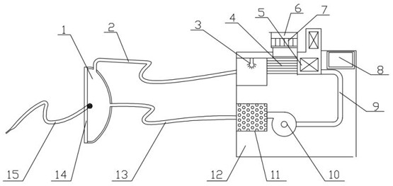
[0023] As shown in the drawings, the present invention includes a transparent cover 1 arranged outside the casing 12, a return air duct 2, a blowpipe 13, a sealing ring 14 and an elastic band 15, and a sterilizing device 3 arranged in the casing 12, Cooler 4, dehumidifier 5, fan 6, heat sink 7, power controller 8, connecting pipe 9, fan 10 and activated carbon adsorption box 11;
[0024] The transparent cover 1 is sequentially connected to the air return pipe 2, the sterilizing device 3, the cooler 4, the dehumidifier 5, the connecting pipe 9, the fan 10, the activated carbon adsorption box 11 and the blowing pipe 13, and the end of the blowing pipe 13 is connected back to the air blowing pipe 13. The transparent cover 1 is used to form a closed air self-circulation cooling drying channel;
[0025] The upper part of the cooler 4 is provided with the heat sink 7 and the fan 6, and the power controller 8 is in communication with the cooler 4, the fan 6 and the blower fan 10; the...
PUM
Abstract
A closed self-circulation burn wound cooling and drying device comprises a transparent cover, an air return pipe, an air blowing pipe, a sealing ring and an elastic bandage which are arranged outsidea shell, and further comprises a sterilization device, a cooler, a dehumidifier, a fan, cooling fins, a power supply controller, a connecting pipe, a fan and an activated carbon adsorption box which are arranged in the shell. The transparent cover is sequentially connected with the air return pipe, the sterilization device, the cooler, the dehumidifier, the connecting pipe, the fan, the activatedcarbon adsorption box and the air blowing pipe, and the tail end of the air blowing pipe is connected back to the transparent cover to form a closed air self-circulation cooling and drying channel. The closed self-circulation burn wound cooling and drying device is low in use cost, wide in application range and bright in application prospect. When a power supply is connected, the temperature, humidity and wind speed of air in a closed self-circulation system can be adjusted. Dressing and medicine are not used, ice species do not need to be frequently added or ice bags do not need to be frequently replaced, use is easy and convenient, and comprehensive benefits are obvious.
Description
technical field [0001] The invention relates to the field of medical equipment, in particular to a closed self-circulation burn wound cooling and drying device. Background technique [0002] In the medical field, when a patient is subjected to local burns or scalds, the wound is painful and prone to exudate and infection. When using cold compresses such as ice packs, the ice packs condense the water vapor in the air to form water droplets, and the water droplets are more likely to be infected when they come into contact with the wound. Use a dressing to cool down the wound. Because the dressing directly contacts the wound, the exudate will soak the dressing quickly, and the wound cannot be kept dry, which may easily cause inflammation, or the dressing will adhere to the wound. Therefore, there is a need for a device that can continuously cool down and dry the wound without touching the wound, isolate bacteria and dust in the ambient air, reduce the exudate of the wound, and...
Claims
Application Information
Patent Timeline
Application Date:The date an application was filed.
Publication Date:The date a patent or application was officially published.
First Publication Date:The earliest publication date of a patent with the same application number.
Issue Date:Publication date of the patent grant document.
PCT Entry Date:The Entry date of PCT National Phase.
Estimated Expiry Date:The statutory expiry date of a patent right according to the Patent Law, and it is the longest term of protection that the patent right can achieve without the termination of the patent right due to other reasons(Term extension factor has been taken into account ).
Invalid Date:Actual expiry date is based on effective date or publication date of legal transaction data of invalid patent.