Cooling hub structure and cooling fan formed by same

A technology for cooling fans and hubs is applied in the components of pumping devices for elastic fluids, non-variable-capacity pumps, pump devices, etc., and can solve problems such as cost increase, impact on motor performance and life, and motor temperature rise. Achieve the effect of reducing impact, improving heat exchange efficiency, and improving heat dissipation efficiency

Active Publication Date: 2020-12-18
东风博泽汽车系统有限公司
View PDF10 Cites 0 Cited by
  • Summary
  • Abstract
  • Description
  • Claims
  • Application Information

AI Technical Summary

Problems solved by technology

Therefore, the temperature of the motor itself will rise, and the motor needs to be dissipated in time. If it cannot be dissipated in time, it will seriously affect the performance and life of the motor.
[0004] At present, the heat dissipation of the motor is mainly due to the linear ribs in the

Method used


Image

  • Cooling hub structure and cooling fan formed by same
  • Cooling hub structure and cooling fan formed by same
  • Cooling hub structure and cooling fan formed by same

Examples


Embodiment Construction

[0030] The principles and features of the present invention are described below in conjunction with the accompanying drawings, and the examples given are only used to explain the present invention, and are not intended to limit the scope of the present invention.

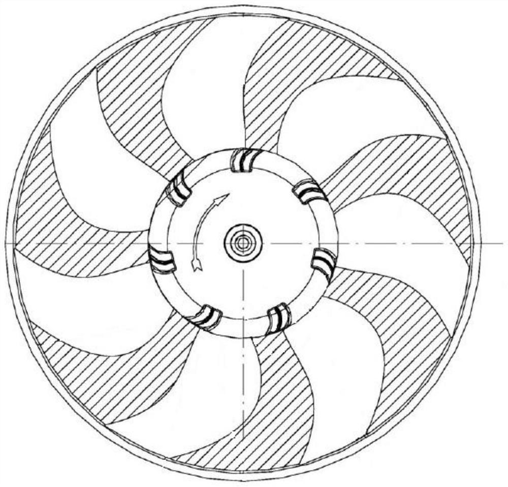
[0031] Patent No. CN207621075U discloses a motor fan heat dissipation hub structure and the cooling fan formed thereof, such as figure 1 As shown, the fan hub is provided with several ventilation slots along the edge, and the fan hub is provided with ventilation holes. The ventilation slots communicate with the motor housing cavity through the ventilation holes, so that the heat inside the motor body is discharged to the outside air under the air flow.

[0032] However, the ventilation holes of the hub of the above-mentioned fan are arranged along the edge of the hub, the area of ​​the hole is small, and the capacity for entering gas is small, and it is a hollow projection structure on the projection plane perpendicu...


PUM


Abstract

The invention relates to a cooling hub structure and a cooling fan formed by the same. Fan blades are arranged on the periphery of the hub structure, a fixed hole is formed in the center of the hub structure and used for being fixedly connected with an output shaft of a fan motor, and a cavity for containing the motor is formed in the hub structure. A plurality of long ventilation holes are formedin the end face, perpendicular to the output shaft of the fan motor, of the hub structure, each long ventilation hole is formed in the radial direction of the hub structure, and the long ventilationholes are used for communicating the cavity with the outer space of the hub structure. The ventilation long holes are formed in the end face of a hub so that the conduction area of the motor and the outside can be increased, outside air can enter the cavity of the hub structure more easily, the heat exchange efficiency is improved, and the influence of heating on the service life of the motor is reduced.

Description

technical field [0001] The invention relates to the technical field of motor heat dissipation, in particular to a novel heat dissipation hub structure for improving heat dissipation of a motor and a heat dissipation fan formed therefrom. Background technique [0002] Radiator fans, such as those used in automotive radiators, condensers and intercoolers, consist of a hub and blades. The hub is connected with the shaft of the driving source motor, and the blades are connected with the outer edge of the hub and arranged along the radial direction. When the driving source motor is energized, the motor shaft drives the hub, and then drives the blades to rotate in the circumferential direction, thereby generating an airflow flowing in the axial direction. When the airflow passes through the radiator, it can cool down the coolant with a higher temperature in the radiator, and the cooled coolant returns to the heat-generating components such as the engine through the corresponding ...

Claims


Application Information

Patent Timeline
IPC IPC(8): F04D29/32F04D29/38F04D29/58
CPCF04D29/329F04D29/327F04D29/384F04D29/5806F04D25/082
Inventor 汤武
Owner 东风博泽汽车系统有限公司
Why Eureka
Try Eureka