Method and system for graphically displaying clock structure

A graphical display and clock technology, which is applied in the direction of instruments, calculations, electrical digital data processing, etc., can solve the problems of fast conversion of the clock structure diagram, slow analysis process, and difficult process, so as to speed up the clock design process and fast and free conversion Effect

Active Publication Date: 2021-05-11
NANJING SEMIDRIVE TECH CO LTD
View PDF5 Cites 0 Cited by
  • Summary
  • Abstract
  • Description
  • Claims
  • Application Information

AI Technical Summary

Problems solved by technology

This takes a lot of time and is even more difficult if other designers need to analyze or modify their clock structures
[0004] At present, with the help of third-party EDA (Electronic design automation, electronic automation design) tools, the clock structure can be automatically graphed, which can facilitate inspection and modification. Tables, library files of all circuit units, and complete timing constraint files and other data are complete.
In the early stage of design, these data are basically not available, usually only part of the RTL (RegisterTransfer Level, register transfer level) code and design architecture diagram, at this time it is impossible to analyze the clock structure through EDA tools
Moreover, this method cannot conveniently and quickly convert the generated clock structure diagram back to the sdc file, so it usually requires a process of multiple iterations such as modification, re-analysis and inspection, return to re-modification, and re-analysis and inspection.
In addition, because the EDA tool needs to read in the information of the entire design, including a lot of information that is not related to the clock structure, the entire analysis process is relatively slow.

Method used


Image

  • Method and system for graphically displaying clock structure
  • Method and system for graphically displaying clock structure
  • Method and system for graphically displaying clock structure

Examples


Embodiment Construction

[0040] The technical solution of the present disclosure will be described in detail below in conjunction with the accompanying drawings. In the description of the present disclosure, it should be understood that the terms "first", "second", and "third" are used for descriptive purposes only, and cannot be interpreted as indicating or implying relative importance or implicitly indicating the indicated The number of technical characteristics is only used to distinguish different components.

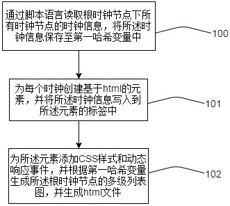
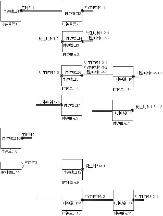
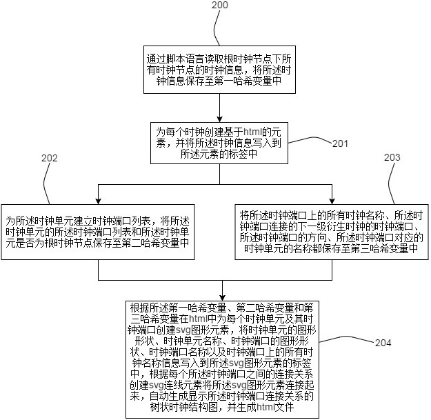
[0041] figure 1 It is a flow chart of the disclosed method, such as figure 1 As shown, 100: read the clock information of all clock nodes under the root clock node through a script language, and save the clock information into the first hash variable. Wherein, the root clock node includes at least one clock unit, and the clock unit includes at least one clock port, and the clock port includes at least one clock, and the clock includes a main clock and a derived clock; the clock informatio...


PUM


Abstract

The invention discloses a method and system for graphically displaying a clock structure, relates to the technical field of chip clock design, and solves the technical problem that a text file containing clock information and a clock structure diagram cannot be freely and quickly converted. The main points of the technical solution are Read the clock information of all clock nodes under the root clock node through a scripting language, save the clock information into the first hash variable; create an html-based element for each clock, and write the clock information into the In the tag of the element; add a CSS style and a dynamic response event to the element, and generate a multi-level list diagram of the root clock node according to the first hash variable, and generate an html file. Fast and free conversion between text files containing clock information and clock multi-level list diagrams is realized, which greatly reduces the iteration time when analyzing and checking clock structures and modifying clock definition information when designing complex clock structure diagrams, and speeds up Clock Design Process.

Description

technical field [0001] The present disclosure relates to the technical field of chip clock design, in particular to a method and system for graphically displaying clock structures. Background technique [0002] At present, with the continuous improvement of the scale and integration of SoC chip design, and the continuous increase of functional diversity, the clock structure in the chip is becoming more and more complex, and the number of clocks is also increasing. It takes a lot of time and energy to analyze, check and modify complex clock structures in chip design, and the error rate is high. The traditional files that describe and define the clock structure are all in plain text format. The clock information and interrelationships can only be recorded in the file one by one through text characters, and the clock information and interrelationships cannot be displayed graphically; and if the clock is manually completed The drawing of the structural diagram takes a lot of ti...

Claims


Application Information

Patent Timeline
Patent Type & Authority Patents(China)
IPC IPC(8): G06F30/392
CPCG06F30/392
Inventor 江小帆
Owner NANJING SEMIDRIVE TECH CO LTD
Why Eureka
Try Eureka