Fuel cell stack assembly

A technology of fuel cell stacks and components, which is applied in the direction of fuel cells, fuel cell parts, electrical components, etc., and can solve the problems of shortening the service life of the collector plate, increasing the production cost of the collector plate, and reducing the volume specific power density, etc. , to achieve the effect of avoiding volume specific power density, increasing production cost and prolonging service life

Pending Publication Date: 2020-12-18
国鸿氢能科技(嘉兴)股份有限公司
View PDF0 Cites 0 Cited by
  • Summary
  • Abstract
  • Description
  • Claims
  • Application Information

AI Technical Summary

Problems solved by technology

[0004] 2. Since the shape of the collector plate and the end plate are the same, both have three-cavity inlet and outlet, so that the collector plate will directly contact with the reaction gas and cooling liquid, which will easily cause corrosion of the collector plate during use and shorten the collector plate service life
[0005] 3. The current collecting plate adopts the side current collecting method. If the flow area of ​​the collecting plate needs to be increased, the only way to increase the thickness of the collecting plate is to increase the production cost of the collecting plate and increase the current collecting plate. The thickness of the stack will lead to an increase in the volume of the outer packaging of the stack, which indirectly reduces the volume specific power density

Method used


Image

  • Fuel cell stack assembly
  • Fuel cell stack assembly
  • Fuel cell stack assembly

Examples


Embodiment Construction

[0029] The technical solutions in the embodiments of the present invention will be clearly and completely described below in conjunction with the accompanying drawings in the embodiments of the present invention. Obviously, the described embodiments are only some, not all, embodiments of the present invention. Based on the embodiments of the present invention, all other embodiments obtained by persons of ordinary skill in the art without creative efforts fall within the protection scope of the present invention.

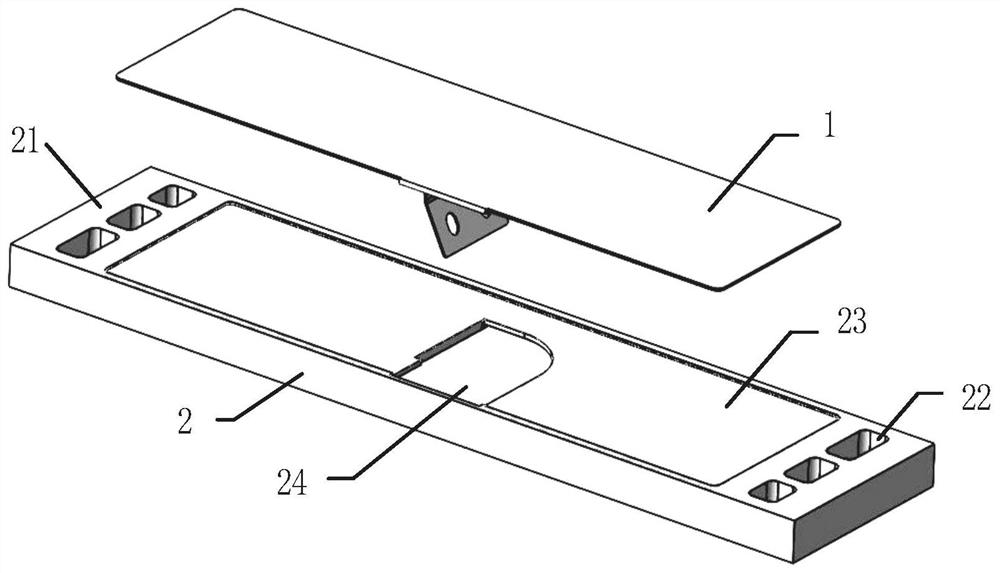
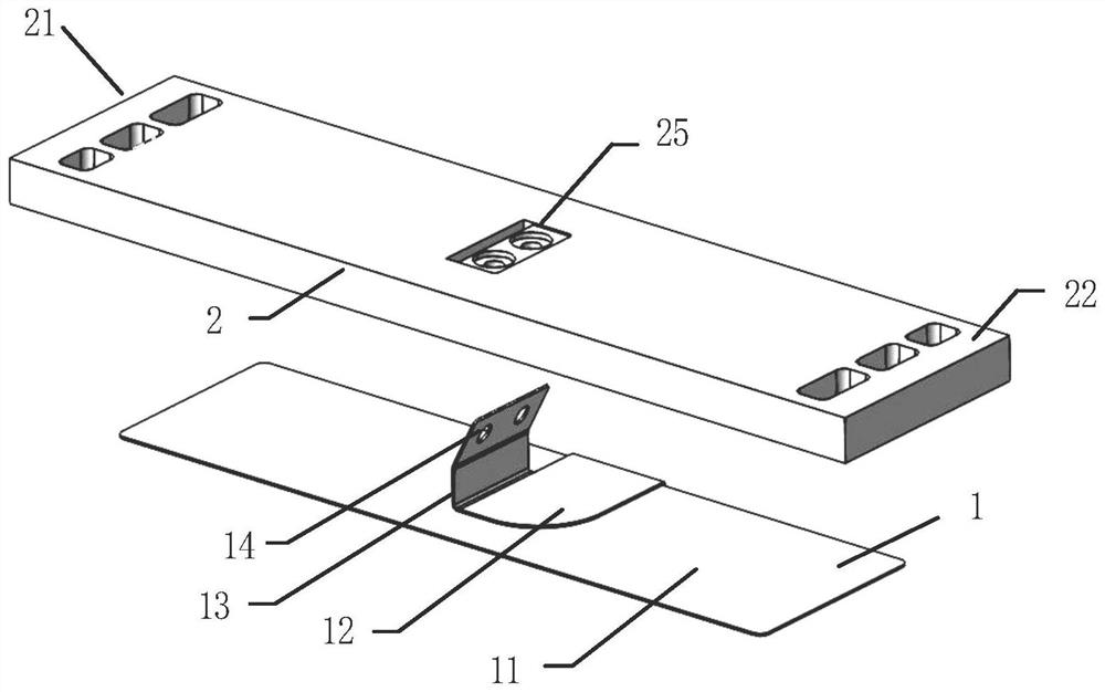
[0030] See Figure 1-4 , the embodiment of the present invention provides a fuel cell stack assembly, including an end plate 2 and a collector plate 1; the collector plate 1 includes a collector plate body 11 and a connecting part; the connecting part includes a first connecting part 12, a second The connecting part 13, the third connecting part 14;

[0031] One end of the first connecting portion 12 is connected to one side of the collector plate body 11 through a ...


PUM


Abstract

The invention provides a fuel cell stack assembly. The fuel cell stack assembly comprises an end plate and a collector plate, the collector plate comprises a collector plate body and a connecting part; the connecting part comprises a first connecting part, a second connecting part and a third connecting part; a first ventilation part is arranged at one end of the end plate, and a second ventilation part is arranged at the other end of the end plate; a first groove allowing the collector plate body to be embedded therein is formed in the position, between the first ventilation part and the second ventilation part, of one face of the end plate, a second groove allowing the first connecting part to be embedded therein is formed in the first groove, a third groove is formed in the other face of the end plate, and the third connecting part penetrates through the insertion hole from one face of the end plate and then is buckled into the third groove. By changing the structure of the galvanicpile assembly, the size of the galvanic pile is reduced, the service life of the galvanic pile collector plate is prolonged, and the overflowing area of the collector plate can be increased on the premise that the external packaging size of the galvanic pile is not increased.

Description

technical field [0001] The invention relates to the technical field of fuel cells, in particular to a fuel cell stack assembly. Background technique [0002] The structure of fuel cell electric drive mainly includes: end plate, collector plate, bipolar plate, several membrane electrodes + bipolar plate, etc. The existing stack structure has the following disadvantages: [0003] 1. The combination of current collector plate and end plate is to use the current collector plate and end plate with the same area for superposition combination. In this combination, the thickness of the stack is the sum of the thickness of the current collector plate and the end plate, so that the stack Larger volume. [0004] 2. Since the shape of the collector plate and the end plate are the same, both have three-cavity inlet and outlet, so that the collector plate will directly contact with the reaction gas and cooling liquid, which will easily cause corrosion of the collector plate during use a...

Claims


Application Information

Patent Timeline
Patent Type & Authority Applications(China)
IPC IPC(8): H01M8/0202H01M8/1004H01M8/0289H01M8/0273
CPCH01M8/0202H01M8/0273H01M8/0289H01M8/1004Y02E60/50
Inventor 王铎霖燕希强王继明崔士涛孙驻江辛猛黄振旭熊承盛陈晓敏
Owner 国鸿氢能科技(嘉兴)股份有限公司
Why Eureka
Try Eureka