Supercharge Your Innovation With Domain-Expert AI Agents!

Device and method for parallel control of lasers and laser marking machine

A parallel control, laser technology, used in laser welding equipment, manufacturing tools, welding equipment, etc., can solve problems such as low printing efficiency

Pending Publication Date: 2020-12-22
湖南鼎一致远科技发展股份有限公司
View PDF8 Cites 0 Cited by
  • Summary
  • Abstract
  • Description
  • Claims
  • Application Information

AI Technical Summary

Problems solved by technology

[0002] At present, the laser marking machine performs image processing on the preset printing pattern, that is, it decomposes the preset printing pattern into multiple printing points according to the preset spacing density. When the laser head of the laser marking machine moves horizontally relative to the substrate, it prints point by point. Specifically: when printing any line, if the point to be printed is a print point, the laser head is controlled to emit The laser beam is sent to the substrate to burn the substrate. If the point to be printed is not a print point, the laser head is controlled not to send the laser beam to the substrate, that is, the substrate is not burned, and then the next line of printing is carried out , until the preset printing pattern is printed on the substrate, since it needs to be printed line by line and point by point, the printing efficiency is low

Method used


Image

  • Device and method for parallel control of lasers and laser marking machine
  • Device and method for parallel control of lasers and laser marking machine

Examples


Embodiment Construction

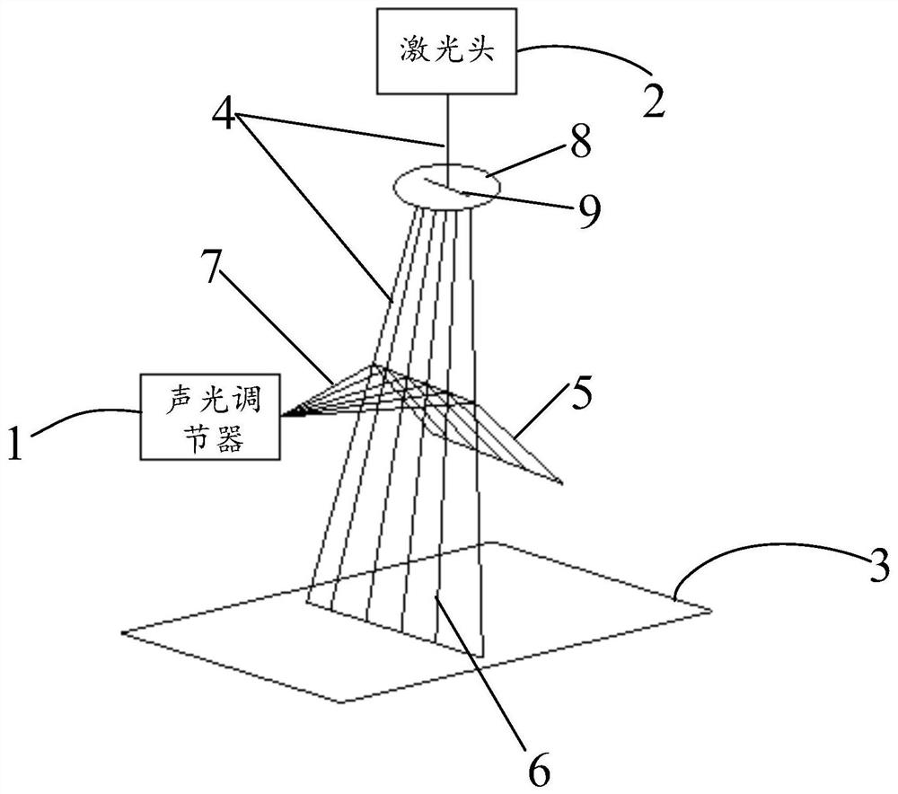
[0033] Such as figure 1 As shown, a parallel laser control device according to an embodiment of the present invention includes an acousto-optic modulator 1 and a laser head 2;

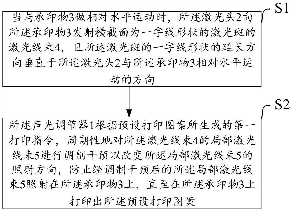
[0034] The laser head 2 is used to emit a laser beam 4 with a cross-section of a laser spot in the shape of a line to the substrate 3 when it moves relatively horizontally with the substrate 3, and the shape of the laser spot is in the shape of a line The extension direction is perpendicular to the relative horizontal movement direction of the laser head 2 and the substrate 3;

[0035] The acousto-optic modulator 1 is used for periodically modulating the local laser beam 5 of the laser beam 4 according to the first printing instruction generated by the preset printing pattern to change the local laser beam 5 The irradiation direction prevents the modulated intervening partial laser beam 5 from irradiating the substrate 3 until the preset printing pattern is printed on the substrate 3 .

[0036] When ...


PUM


Abstract

The invention relates to a device and method for parallel control of lasers and a laser marking machine. When a laser head and a print substrate do relative horizontal movement, the laser head emits laser beams with laser spots of which the cross sections are in a line shape to the print substrate, and an acousto-optic regulator periodically modulates and intervenes into local laser beams of the laser beams to change the irradiation direction of the local laser beams according to a first printing instruction generated by a preset printing pattern. Due to the laser spots with the line-shaped cross sections of the laser beams, the whole line printing can be carried out on the print substrate, and point-by-point printing on each line is not needed, therefore, compared with a previous line-by-line and point-by-point printing mode, the method has the advantage that the printing efficiency is greatly improved.

Description

technical field [0001] The invention relates to the technical field of laser printing, in particular to a device and method for controlling laser in parallel and a laser marking machine. Background technique [0002] At present, the laser marking machine performs image processing on the preset printing pattern, that is, it decomposes the preset printing pattern into multiple printing points according to the preset spacing density. When the laser head of the laser marking machine moves horizontally relative to the substrate, it prints point by point. Specifically: when printing any line, if the point to be printed is a print point, the laser head is controlled to emit The laser beam is sent to the substrate to burn the substrate. If the point to be printed is not a print point, the laser head is controlled not to send the laser beam to the substrate, that is, the substrate is not burned, and then the next line of printing is carried out , until the preset printing pattern is...

Claims


Application Information

Patent Timeline
Patent Type & Authority Applications(China)
IPC IPC(8): B23K26/362
CPCB23K26/362
Inventor 李留祥唐国初
Owner 湖南鼎一致远科技发展股份有限公司
Features
  • R&D
  • Intellectual Property
  • Life Sciences
  • Materials
  • Tech Scout
  • Unparalleled Data Quality
  • Higher Quality Content
  • 60% Fewer Hallucinations
Learn More