
Multi-drill-bit wall surface automatic drilling equipment

A kind of drilling equipment and multi-drill technology, which is applied in the direction of stone processing equipment, stone processing tools, working accessories, etc., can solve the problems of non-straight drilling, high operation difficulty, and large dust, so as to reduce the construction risk and reduce the Difficulty in operation, effect of reducing dust pollution

Inactive Publication Date: 2020-12-22
天津勇刚锁具销售有限公司
View PDF0 Cites 2 Cited by
  • Summary
  • Abstract
  • Description
  • Claims
  • Application Information

AI Technical Summary

Problems solved by technology

[0002] In the decoration of new houses or in daily life, there is a great demand for drilling holes on the wall. At present, most of the wall drilling is done by manual hand-held electric drills, but ordinary hand-held electric drills are noisy and dusty, and because they are manually operated, Therefore, after manual drilling, the drilling may not be straight or the force may be uneven when drilling, resulting in damage to the wall and affecting the aesthetics of the wall.
And in life, holes of different diameters are often required to meet the installation of some architectural decorations. It is usually necessary to manually replace the drill bit after drilling a hole and continue drilling, resulting in low work efficiency.
Moreover, when drilling holes on the wall, hand-held electric drills are more dangerous and difficult to operate. Wall drilling often needs to be operated by professionals, resulting in weak functions

Method used


Image

  • Multi-drill-bit wall surface automatic drilling equipment
  • Multi-drill-bit wall surface automatic drilling equipment
  • Multi-drill-bit wall surface automatic drilling equipment

Examples


Embodiment Construction

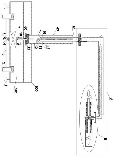
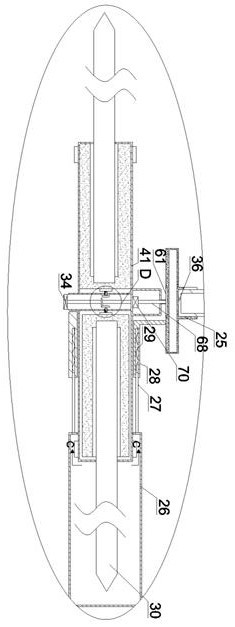
[0019] Combine below Figure 1-5 The present invention is described in detail, wherein, for the convenience of description, the orientations mentioned below are defined as follows: figure 1 The up, down, left, right, front and back directions of the projection relationship itself are the same.

[0020] combined with Figure 1-5 The multi-bit wall automatic drilling equipment includes a main body 900, a power chamber 901 is provided in the main body 900, a biaxial motor 7 is arranged inside the power chamber 901, and a biaxial motor 7 is provided with Extending down to the first motor shaft 6 outside the power chamber 901, the first motor shaft 6 is fixed with a first bevel gear 5, and the lower side of the main body 900 is provided with a travel wheel 2 that is front, rear, left, and right symmetrical. A travel shaft 3 is hinged between the travel wheels 2, and a second bevel gear 4 is fixedly mounted on the travel shaft 3, and the second bevel gear 4 meshes with the first b...


PUM


Abstract

The invention discloses multi-drill-bit wall surface automatic drilling equipment. The multi-drill-bit wall surface automatic drilling equipment comprises a body, a power cavity is formed in the body,a double-shaft motor is arranged in the power cavity, a first motor shaft downwards extending out of the power cavity is arranged on the double-shaft motor, a first bevel gear is fixedly arranged onthe first motor shaft, advancing wheels in front-and-back and left-and-right symmetry are arranged on the lower side of the body, an advancing shaft is hinged between the advancing wheels, and a second bevel gear is fixedly arranged on the advancing shaft. A plurality of drill bits can be installed, automatic switching can be achieved according to the requirements for the sizes of holes, a dustproof mechanism is arranged, the situation that dust is large in the drilling process can be avoided, the drilling equipment can automatically advance and automatically ascend or descend according to theheights of the hole positions, and drilling is automatically completed. The drilling efficiency is greatly improved, dust pollution during drilling construction is reduced, the operation difficulty of the equipment is reduced, and the construction risk is reduced.

Description

technical field [0001] The invention relates to a multi-drill wall automatic punching device, and mainly relates to the technical field of building decoration equipment. Background technique [0002] In the decoration of new houses or in daily life, there is a great demand for drilling holes on the wall. At present, most of the wall drilling is done by manual hand-held electric drills, but ordinary hand-held electric drills are noisy and dusty, and because they are manually operated, Therefore, after manual drilling, the drilling may not be straight or the force may be uneven when drilling, resulting in damage to the wall surface and affecting the aesthetics of the wall surface. And in life, holes of different diameters are often needed to meet the installation of some architectural decorations. Usually, after drilling a hole, the drill bit needs to be manually replaced to continue drilling, resulting in low work efficiency. And when drilling holes on the wall, the hand-hel...

Claims


Application Information

Patent Timeline
Patent Type & Authority Applications(China)
IPC IPC(8): B28D1/14B28D7/00B28D7/02
CPCB28D1/14B28D7/00B28D7/005B28D7/02
Inventor 起亚萍
Owner 天津勇刚锁具销售有限公司
Learn More