Method for positioning and controlling assembling and disassembling of bending die based on computer vision system

A technology of computer vision and bending molds, applied in the field of vision, can solve problems such as large measurement errors, poor real-time performance, and low measurement accuracy, and achieve the effects of high product quality, fast speed, and improved bending success rate

Pending Publication Date: 2020-12-22
HEFEI UNIV OF TECH
View PDF12 Cites 2 Cited by
  • Summary
  • Abstract
  • Description
  • Claims
  • Application Information

AI Technical Summary

Problems solved by technology

Therefore, accurately detecting and controlling the bending angle of the workpiece is of great significance for improving the quality and production efficiency of the bending of the workpiece. The traditional methods of measuring the angle include: mechanical measurement method, electromagnetic measurement method, optical measurement method and photoelectric measurement method. These methods have the limitations of low measurement accuracy, insufficient real-time performance, and inability to implement non-contact measurement.
The principle of the mechanical measurement method is simple and easy to understand, but this method has disadvantages that cannot be ignored, that is, the me

Method used


Image

  • Method for positioning and controlling assembling and disassembling of bending die based on computer vision system
  • Method for positioning and controlling assembling and disassembling of bending die based on computer vision system
  • Method for positioning and controlling assembling and disassembling of bending die based on computer vision system

Examples


Embodiment Construction

[0047] The following will clearly and completely describe the technical solutions in the embodiments of the present invention with reference to the accompanying drawings in the embodiments of the present invention. Obviously, the described embodiments are only some, not all, embodiments of the present invention. Based on the embodiments of the present invention, all other embodiments obtained by persons of ordinary skill in the art without making creative efforts belong to the protection scope of the present invention.

[0048] The present invention provides a method for locating and controlling the loading and unloading of bending molds based on a computer vision system, which includes a computer vision system and control operation steps, and the control operation steps include:

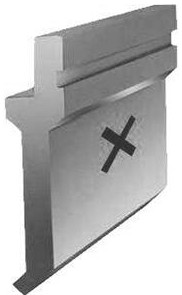
[0049] Step 1: Place a camera at the position directly in front of the bending machine and in front of the mold library where the entire scope of the bending mold can be photographed, respectively re...


PUM


Abstract

The invention relates to a method for positioning and controlling assembling and disassembling of a bending die based on a computer vision system. The method comprises the computer vision system and the steps of control operation, and cameras are placed right in front of a bending machine and a die library respectively. A bending machine with the length of 2m is take as an example, cross-shaped machine tool locators are attached to the same bending die hydraulic clamping strip at intervals of 20cm; a die identifier is attached to the center of each die; a master control system sends a die image acquisition instruction to a camera module, the cameras shoot and return an image to a database, and corresponding relations between different identifiers and the dies are stored in the database. animage recognition algorithm is adopted to calculate the positions of the bending die needing to be disassembled and the bending die needing to be assembled on the bending machine tool and in the dielibrary, and calculate the angle needing to be rotated next and the translation amount according to the angle and the position of a product in a shooting position; a mechanical arm places the productaccording to the calculation result; and after the mechanical arm accurately places the product according to the instruction, the bending success rate is increased.

Description

technical field [0001] The invention relates to the field of vision technology, in particular to a method for positioning and controlling the loading and unloading of bending molds based on a computer vision system. Background technique [0002] Bending machine is the key equipment for high-precision bending of high-strength plates in industries such as automobiles and shipbuilding. In order to make the bent sheet well meet the requirements of the forming angle, it is necessary to quickly and accurately obtain the bending angle of the sheet in a complex background environment. The bending of sheet metal is an important processing method in the sheet metal processing industry. As an important carrier for sheet metal forming, bending machines have been widely used in sheet metal processing. With the continuous improvement of industrial production technology and processing technology, people put forward higher and higher requirements for the accuracy of sheet forming angle. T...

Claims


Application Information

Patent Timeline
IPC IPC(8): B30B15/02B21D37/14B21C51/00
CPCB30B15/028B21D37/14B21C51/00
Inventor 李亨李润王玉山田开国吴玉程
Owner HEFEI UNIV OF TECH
Why Eureka
Try Eureka