
Safety protection type new energy charging pile

A technology for safety protection and charging piles, applied in charging stations, electric vehicle charging technology, electric vehicles, etc., can solve the problems of increasing safety hazards in the installation site of charging piles, reducing the safety of charging piles, and reducing the service life of cables. , to achieve the effect of promoting and popularizing, using safe and convenient, and optimizing the use process.

Inactive Publication Date: 2020-12-22
邹思良
View PDF8 Cites 2 Cited by
  • Summary
  • Abstract
  • Description
  • Claims
  • Application Information

AI Technical Summary

Problems solved by technology

[0004] The present invention provides a safety-protected new energy charging pile, which can effectively solve the problem that the exposed cables lack corresponding protection due to the lack of a corresponding cable storage mechanism in the charging pile proposed in the above background technology, so that during the idle process It will be damaged by wind, sun, sun and other external forces, thereby reducing the service life of the cable. At the same time, the cable will hang down to the ground during use and idle, and it is easy for users to use charging piles or pedestrians passing by charging piles. Tripping over the cables reduces the safety of the charging pile and increases the safety hazards of the charging pile installation site

Method used


Image

  • Safety protection type new energy charging pile
  • Safety protection type new energy charging pile
  • Safety protection type new energy charging pile

Examples


Embodiment

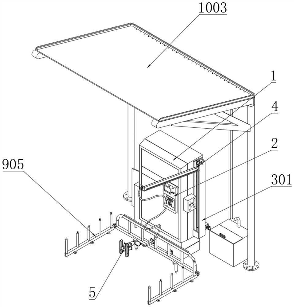
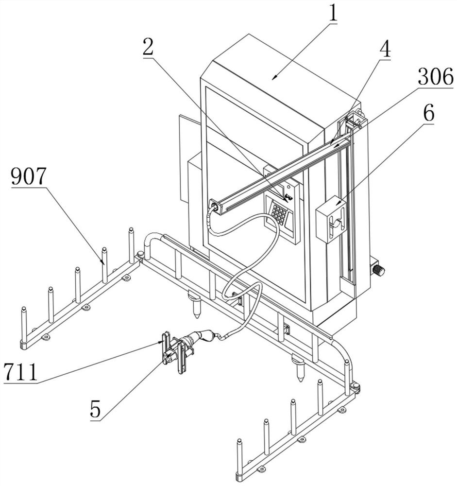
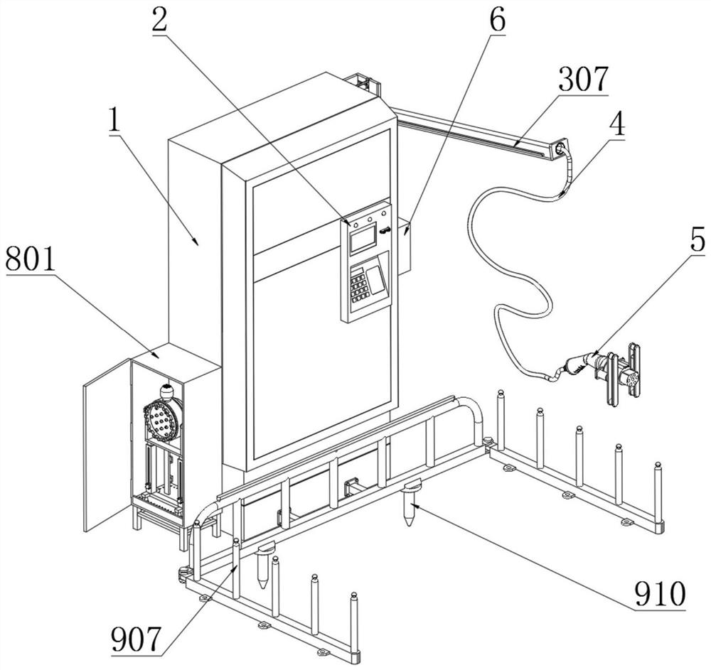
[0044]Example: such asFigure 1-9As shown, the present invention provides a technical solution, a safety protection type new energy charging pile, including a charging pile main body 1, a control panel 2 is provided on the front side of the charging pile main body 1, and a cable is provided on one side of the charging pile main body 1 Overhead mechanism 3;

[0045]The cable overhead mechanism 3 includes a storage vertical box 301, a guide vertical slot 302, a limiting bolt 303, a traction sliding column 304, a connecting frame 305, a supporting flip plate 306, a limiting arc rod 307, a guiding orifice 308, and a limiting guide Column 309, mounting box 310, drive motor 311, drive shaft 312, take-up wheel 313 and traction rope 314;

[0046]A storage vertical box 301 is fixedly connected to a position on one side of the charging pile body 1, and a guide vertical slot 302 is opened on both sides of the storage vertical box 301. The top of the storage vertical box 301 corresponds to the inner s...


PUM


Abstract

The invention discloses a safety protection type new energy charging pile. A control panel is arranged on one side of the front surface of a charging pile main body; an accommodating vertical box is fixedly connected to the position of one side of the charging pile main body; guide vertical grooves are formed in the middles of the two sides of the interior of the accommodating vertical box; and alimiting bolt is connected with the top, corresponding to the guide vertical grooves, of the accommodating vertical box through a thread in a penetrating manner. According to the charging pile, a cross beam is erected at the top of the front face of the storage vertical box through a completely-lifted supporting turnover plate, so that a power transmission cable is distributed at the top of the supporting turnover plate in the using process of the charging pile, an arch-shaped channel is formed in one side of the accommodating vertical box, a user can pass through the bottom of the supportingturnover plate in the charging process, the power transmission cable is effectively prevented from being drooped between an automobile and the charging pile main body in the using process of the charging pile, the phenomenon that the user is stumbled and injured by the power transmission cable in the process of using the charging pile is effectively avoided, and the using process of the charging pile is optimized.

Description

Technical field[0001]The invention relates to the technical field of charging piles, in particular to a safety protection type new energy charging pile.Background technique[0002]The function of the charging pile is similar to the filling machine in the gas station. It can be fixed on the ground or wall and installed in the parking lot or charging station of public buildings and residential quarters. It can charge various types of electric vehicles according to different voltage levels. The input terminal is directly connected to the AC grid, and the output terminal is equipped with a charging plug for charging electric vehicles. Charging piles generally provide two charging methods: conventional charging and fast charging. People can use specific charging cards to provide people in the charging piles. Swipe the card on the machine interactive operation interface to perform operations such as the corresponding charging method, charging time, and cost data printing. The charging pile ...

Claims


Application Information

Patent Timeline
Patent Type & Authority Applications(China)
IPC IPC(8): B60L53/31B60L53/16E04H1/12E03B3/02E03F5/10B65H75/44F26B21/00F24H3/04F24H9/18F24H9/00B08B5/02
CPCB08B5/02B65H75/44B65H2701/34B60L53/16B60L53/31E03B3/02E03F5/10E04H1/1238F24H3/0405F24H9/0057F24H9/1863F26B21/001Y02T10/70Y02T10/7072Y02T90/12Y02T90/14Y02A20/108
Inventor 邹思良
Owner 邹思良
Learn More