[0035]The present invention will be described in detail below with reference to the drawings and specific embodiments. Herein, the present invention will be illustrated in detail. The present invention will be described in detail with reference to the drawings and specific embodiments. To explain the present invention, but not as a limitation to the present invention.
[0036]It should be noted that all directional indicators (such as up, down, left, right, front, back, upper end, lower end, top, bottom...) in the embodiments of the present invention are only used to explain that they are in a specific posture (as shown in the drawings). If the specific posture changes, the relative positional relationship, movement, etc. of the components below will also change the directional indication accordingly.
[0037]In the present invention, unless otherwise clearly specified and limited, the term "connected" should be understood in a broad sense. For example, "connected" can be a fixed connection, a detachable connection, or a whole; it can be a mechanical connection or It may be an electrical connection; it may be directly connected or indirectly connected through an intermediate medium, and it may be the internal communication between two elements or the interaction relationship between two elements, unless specifically defined otherwise. For those of ordinary skill in the art, the specific meanings of the above terms in the present invention can be understood according to specific circumstances.
[0038]In addition, in the present invention, descriptions involving "first", "second", etc. are only for descriptive purposes, and cannot be understood as indicating or implying their relative importance or implicitly indicating the number of indicated technical features. Therefore, the features defined with “first” and “second” may explicitly or implicitly include at least one of this feature; in addition, the technical solutions between the various embodiments can be combined with each other, but they must be based on common techniques in the field. Personnel's realization is the basis, and when the combination of technical solutions is contradictory or cannot be realized, it should be considered that such a combination of technical solutions does not exist, nor does it fall within the protection scope of the present invention.
[0039]Such asFigure 1 to Figure 10As shown, a construction method for connecting nodes of prefabricated Bailey frame steel pipe column foundation includes the following steps:
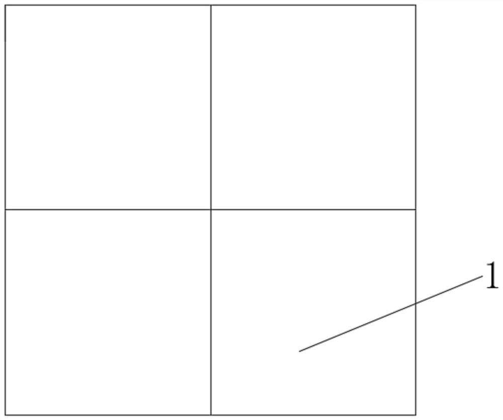
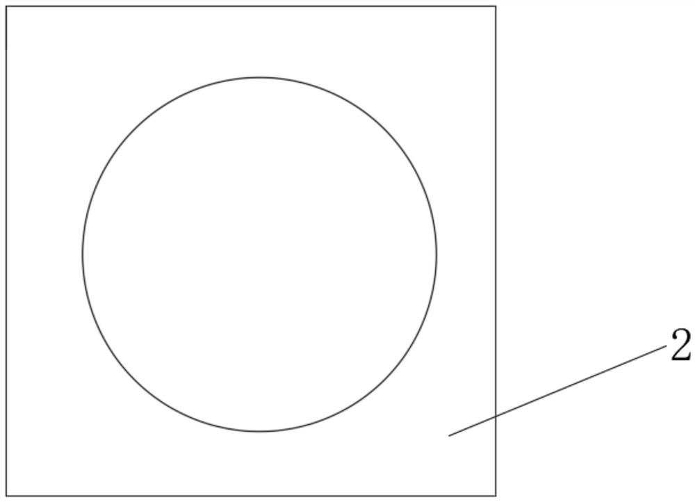
[0040]Step A: Prepare two steel plates of the same specification; the first steel plate 1 is pre-embedded and arranged by foundation casting; the middle of the second steel plate 2 is cut with a central hole whose diameter is the outer diameter of the steel pipe for subsequent overlap with the steel pipe column 3; Referencefigure 1; Mark the two symmetry axes on the first steel plate 1.
[0041]Step B: Bind the foundation steel bar 4, and weld the first steel plate 1 in step A to the foundation steel bar 4 through the connecting bars 5; the prefabricated foundation 6 is placed on a horizontal ground, and the first steel plate 1 is fixed to the foundation 6. Adjust the level of the first steel plate 1 with a ruler to ensure that the welding and fixing of the first steel plate 1 is level and firm, and does not shift when pouring concrete to ensure the levelness of the first steel plate 1. It should be noted that the level of the first steel plate 1 is strictly controlled. The key to ensuring verticality in the later stage. Please refer toFigure 4.
[0042]Step C: Pour concrete on the first steel plate 1, and try not to touch the embedded parts and the foundation reinforcement 4 during the vibrating process;
[0043]Step D: Weld the second steel plate 2 with the pre-opened center hole in step A with the steel pipe column 3, and sleeve the steel pipe column 3 into the center hole of the second steel plate 2, and the cross section of the steel pipe column 3 is flush with the bottom surface of the second steel plate 2; Previously, the welding surface of the steel pipe column 3 is required to be flat, and the welding surface is perpendicular to the axis of the steel pipe column 3, which is combined with the control of the levelness of the first steel plate 1 in step B to ensure the verticality of the steel pipe column 3 and avoid the eccentric force of the steel pipe column 3 later; Please refer toFigure 5 ,Figure 6.
[0044]Step E: Making prefabricated sockets, find the two axes of the first steel plate 1 embedded in the foundation 6, and measure the inner diameter of the steel pipe column 3, add three vertical steel plates on the outer side wall of the steel pipe column 3, the first vertical steel plate 7 Welded to the transverse axis of the first steel plate 1; the second vertical steel plate 8 and the third vertical steel plate 9 are respectively welded to the two ends of the vertical axis of the first steel plate 1; the top of the vertical steel plate is welded with multiple stiffeners 10 ;Please refer toFigure 7 ,Figure 8.
[0045]Step F: Wrap a circle of plastic film in the circumferential direction of the socket, fix it with tape, use a hoist to lift the steel pipe column 3, install the steel pipe column 3 to the socket, naturally lower it, and firmly combine with the socket until the first steel plate 1 and The upper surface of the second steel plate 2 overlaps with no gap in the middle to complete the installation. It should be noted that during installation and positioning, the steel pipe column 3 is lifted by a crane and assembled with the basic socket; the boundary between the first steel plate 1 and the second steel plate 2 is required to overlap, the gap between the steel plate and the steel plate is checked, and the surface installation is qualified without gaps; The steel pipe is flat to ensure the verticality of the steel pipe, and the superstructure load is transmitted to the foundation 6, without eccentric force. The width of the steel plate of the foundation socket is the same as the inner diameter of the steel pipe column 3, which restricts the circumferential movement and the joint is stable and reliable. ReferencePicture 9 withPicture 10.
[0046]It should be noted that by improving the joint form of the steel pipe column 3 and the foundation, the installation only needs to be connected with the socket by a crane. The installation is simple and fast; the improved connection joint is completed at one time, avoiding repeated cutting of the steel pipe in the later stage, and the welding is long, and the quality is easy Guarantee; through the pre-embedded steel plate level and the vertical control of the steel pipe and steel plate in the prefabricated foundation 6, the verticality of the entire system is ensured, and the impact of the installation on the verticality of the system is avoided, so that the steel pipe Bailey frame system is stable and safe purpose.
[0047]Specifically, in the solution of this embodiment, in the step A, the specifications of the first steel plate 1 and the second steel plate 2 are steel plates with a length of 90 cm, a width of 90 cm, and a thickness of 2 cm. It should be noted that although this scheme takes a fixed foundation and component dimensions as an example, in practice, due to different superstructure loads, the bearing capacity of the foundation changes accordingly, and the dimensions of the foundation and steel plates can be adjusted accordingly. It can also be used for temporary buttress foundations such as steel box girder.
[0048]Specifically, in the solution of this embodiment, in the step B, the welding length between the first steel plate 1 and the base steel bar 4 meets the requirement of 5 times the diameter of the base steel bar 4 on both sides and 10 times the diameter of the base steel bar 4 on one side.
[0049]Specifically, in the solution of this embodiment, in the step D, four triangular stiffeners 11 are welded at 90° intervals on the outer side of the steel pipe column 3 at the same time, and the steel pipe column 3, the second steel plate 2 and the triangular stiffener 11 are filled with each other. Welding, welding quality meets the requirements of corresponding specifications.
[0050]Specifically, in the solution of this embodiment, in the step E, the width and height of the first vertical steel plate 7 are equal to the inner diameter of the steel pipe column 3; the sum of the widths of the second vertical steel plate 8 and the third vertical steel plate 9 is equal to the steel pipe The inner diameter of column 3. It should be noted that the width of the vertical steel plate is consistent with the inner diameter of the steel pipe column 3 in order to limit the circumferential sliding of the steel pipe column 3, and the gravity of the steel pipe column 3 is vertical to ensure that it does not shift.
[0051]Specifically, in the solution of this embodiment, in the step E, the four corners of the top of the vertical steel plate are all set in an arc shape, which facilitates the insertion of the steel pipe column 3 and reduces the installation difficulty.
[0052]Specifically, in the solution of the present embodiment, in the step B, the layout points of the foundation 6 are located by measuring and laying out, and two axes are released at the installation points of the foundation 6 to locate the position of the foundation 6.
[0053]Specifically, in the solution of the present embodiment, in the step B, the foundation 6 is leveled with mortar on the ground, and the level of the embedded steel plate surface of the foundation is measured with a spirit level before the next step of construction can be carried out. It should be noted that the verticality is very important to the force of the structural system. The embedded steel plate of the foundation of this construction method is parallel to the bottom of the foundation 6. Keep the ground level to ensure the level of the steel plate and ensure that the entire system has a good force effect.
[0054]Specifically, in the solution of this embodiment, in the step E, four stiffening ribs 10 are provided; the four stiffening ribs 10 are welded in the first vertical steel plate 7, the second vertical steel plate 8 and the third vertical The top of the steel plate 9.
[0055]Specifically, in the solution of this embodiment, the step F further includes the disassembly of the steel pipe column 3, the steel pipe column 3 is lifted by a crane, and the two are naturally separated by the gravity of the foundation 6.
[0056]The present invention transforms the existing beret steel pipe column and the prefabricated foundation to realize repeatable turnover. Compared with the existing foundation, the installation and positioning need to use a crane, the positioning is difficult, and the welding connection is prone to misalignment and affects the force. The optimized connection joint is only centered and socketed through the steel pipe column 3 and the basic prefabricated socket, and the steel plate is connected to the steel plate. The contact surface is stable, the installation is simple, easy to operate, the construction is fast, the joint is firmly connected, and the repeated cutting of steel pipe and welding process are avoided. The force effect is good, and the quality and safety are easy to guarantee.
[0057]The technical solutions provided by the embodiments of the present invention are described in detail above. Specific examples are used in this article to describe the principles and implementation modes of the embodiments of the present invention. The descriptions of the above embodiments are only applicable to help understanding of the embodiments of the present invention. Principle; At the same time, for those of ordinary skill in the art, according to the embodiments of the present invention, there will be changes in the specific implementation and the scope of application. In summary, the content of this specification should not be construed as limiting the present invention.