Air inlet self-cleaning system for engineering machinery

A construction machinery and self-cleaning technology, applied in the charging system, mechanical equipment, fuel air filter and other directions, can solve the problems of complex self-cleaning air filter structure and long self-blowing time interval, shorten the self-cleaning time, Reduce labor intensity and good reliability

Pending Publication Date: 2020-12-22
SHANDONG LINGONG CONSTR MACHINERY
View PDF0 Cites 2 Cited by
  • Summary
  • Abstract
  • Description
  • Claims
  • Application Information

AI Technical Summary

Problems solved by technology

[0003] The purpose of the present invention is to provide an air intake self-cleaning system for construction machinery to overcome the defects in the prior art that the self-cleaning air filter structure is complex, an air compressor pump is required to provide a high-pressure air source, and the self-blowing time interval is long

Method used


Image

  • Air inlet self-cleaning system for engineering machinery
  • Air inlet self-cleaning system for engineering machinery
  • Air inlet self-cleaning system for engineering machinery

Examples


Embodiment 1

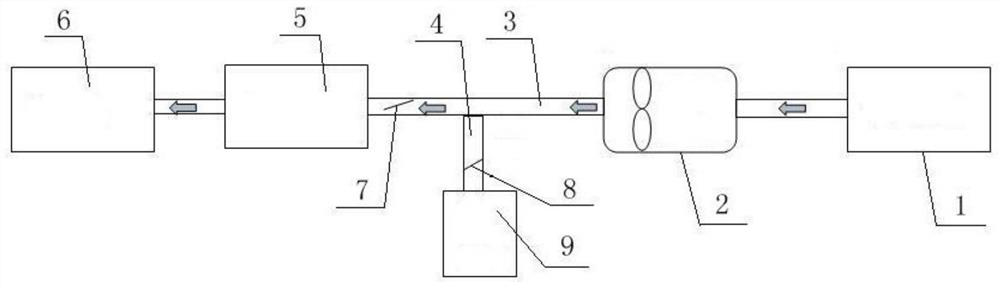
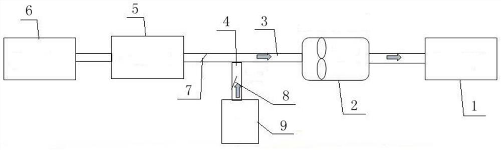
[0020]Example 1: Such asfigure 1 ,figure 2 As shown, the air intake self-cleaning system for construction machinery in this embodiment includes a first-stage dry air filter 1, a main ventilation pipe 3, and a second-stage dry air filter 5. The first-stage dry air filter 1 It is connected with the second-stage dry air filter 5 through the main ventilation pipeline 3. The main ventilation pipeline 3 between the first-stage dry air filter 1 and the second-stage dry air filter 5 is equipped with a duct fan 2. An air inlet pipe 4 is installed at the air inlet of the secondary dry air filter 5, a check valve A7 is provided on the main ventilation pipe 3, and a check valve B8 is provided on the air inlet pipe 4.

[0021]Further, a third-stage dry air filter 9 is connected to the air inlet pipe 4, and the third-stage dry air filter 9 is used to provide a clean air source for the back-blowing process.

[0022]Further, when the rated air volume of the selected duct fan 2 is greater than the intake ...

Embodiment 2

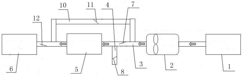
[0026]Example 2: Such asimage 3 ,Figure 4As shown, the air intake self-cleaning system for construction machinery shown in this embodiment includes a first-stage dry air filter 1, a second-stage dry air filter 5, and a main ventilation pipe 3. The first-stage dry air filter 1 It is connected with the second-stage dry air filter 5 through the main ventilation pipe 3 ways. The main ventilation pipe 3 between the first-stage dry air filter 1 and the second-stage dry air filter 5 is equipped with a duct fan 2. An air inlet pipe 4 is installed at the air inlet of the secondary dry air filter 5, a check valve A7 is installed on the main ventilation pipe 3, and a check valve B8 is installed on the air inlet pipe 4; the second stage dry air filter 5 A bypass pipeline 10 is connected between the front and rear ends, a check valve C11 is provided on the bypass pipeline 10, and the main ventilation pipeline 3 between the second-stage dry air filter 5 and the engine 6 is provided Check valve D1...


PUM


Abstract

The invention discloses an air inlet self-cleaning system for engineering machinery, and belongs to the field of air filtering systems. The defects that in the prior art, a self-cleaning air filter iscomplex in structure, an air compression pump is needed for providing a high-pressure air source, and the self-blowing time interval is long are overcome. According to the technical scheme, the air inlet self-cleaning system for engineering machinery is characterized by comprising a first-stage dry type air filter, a main ventilation pipeline and a second-stage dry type air filter, the first-stage dry type air filter is connected with the second-stage dry type air filter through the main ventilation pipeline, a pipeline fan is arranged on the main ventilation pipeline between the first-stagedry type air filter and the second-stage dry type air filter, and an air inlet pipeline is mounted at an air inlet of the second-stage dry type air filter, a check valve A is arranged on the main ventilation pipeline, and a check valve B is arranged on the air inlet pipeline. The air inlet system can be pressurized in the working process of the whole machine, the air inlet resistance of an engineis effectively reduced, and the first-stage air filter can be cleaned and dedusted through back flushing immediately during shutdown.

Description

Technical field[0001]The invention belongs to an air filter system, and specifically relates to an air intake self-cleaning system for engineering machinery.Background technique[0002]The working environment of construction machinery is harsh, and the dusty areas generally use two-stage main air filter (first dry air filter + first oil bath air filter). The first oil bath air filter often needs to be cleaned and the oil pollution is serious. And the cleaning time is long, and the effective working time of the whole machine will be affected by the shutdown. There are also self-cleaning air filters on the market. The first-stage oil-bath air filter is replaced with a dry air filter, and compressed air is used to shut down and blow automatically. The current self-cleaning air filter has a complicated structure and requires an air compression pump to provide a high-pressure air source. The entire shutdown self-blowing time interval is long. When multiple self-blowing, the air compression...

Claims


Application Information

Patent Timeline
Patent Type & Authority Applications(China)
IPC IPC(8): F02M35/08F02M35/02F02M35/024
CPCF02M35/0216F02M35/024F02M35/086
Inventor 刘崇解玉钦李庆鹏张晓伟李姝红孔庆雷贾吉彭田始军
Owner SHANDONG LINGONG CONSTR MACHINERY
Why Eureka
Try Eureka