Optical lens group

An optical lens and lens technology, applied in the field of optics, can solve problems affecting optical quality, etc., and achieve the effects of good thermal stability, large field of view, and good optical quality

Active Publication Date: 2020-12-22
GENIUS ELECTRONICS OPTICAL XIAMEN
View PDF1 Cites 0 Cited by
  • Summary
  • Abstract
  • Description
  • Claims
  • Application Information

AI Technical Summary

Problems solved by technology

In addition, different ambient temperatures may also affect the optical quality
The above problems have become challenges in the development of optical lens groups

Method used


Image

  • Optical lens group
  • Optical lens group
  • Optical lens group

Examples


Embodiment Construction

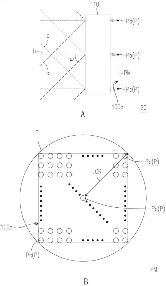
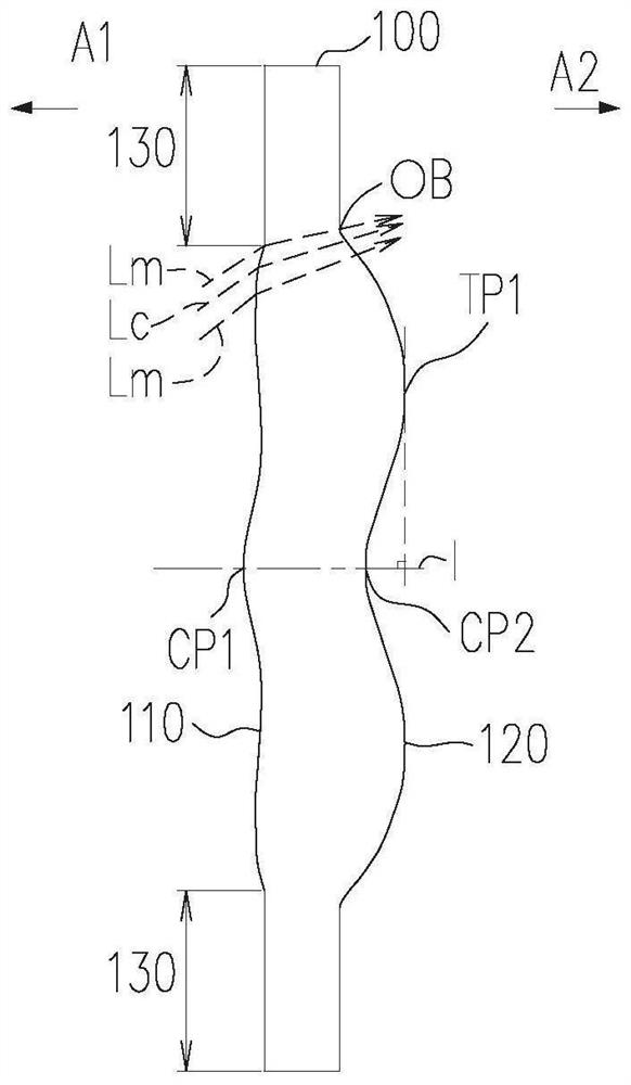
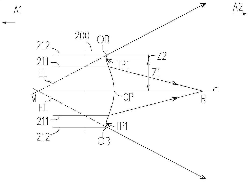
[0061] Before starting to describe the present invention in detail, at first clearly represent the symbol explanation in the accompanying drawings: 0: aperture; 1: the first lens; 2: the second lens; 3: the third lens; 4: the fourth lens; 5: the fifth Lens; 6: the sixth lens; 10: optical lens group; 20: projection lens; 11, 21, 31, 41, 51, 61, 110, 410, 510: the first side; 12, 22, 32, 42, 52 , 62, 120, 320: second side; 100a: reference surface; 100, 200, 300, 400, 500: lens; 130: assembly part; , 415, 417, 425, 427, 515, 517, 525, 615, 617, 625, 627, Z1: optical axis area; , 516, 526, 528, 616, 626, Z2: circumferential area; 211, 212: parallel rays; A1: first side; A2: second side; a, b, c: imaging rays; : first center point; CP2: second center point; EL: extension line; I: optical axis; Lm: marginal ray; Lc: chief ray; LCR: radius of luminous circle; M, R: intersection point; OB: optical boundary ; P, Pa, Pb, Pc: light source; PM: multi-light source generating unit; TP1: f...


PUM


Abstract

The invention provides an optical lens group. The optical lens group sequentially comprises a first lens, a second lens, a third lens, a fourth lens, a fifth lens and a sixth lens from a first side toa second side along an optical axis, wherein the optical lens group satisfies a conditional expression that EFL / BFL is greater than or equal to 3.800. The optical lens group has advantages of being small in size, large in field angle, good in thermal stability and capable of enabling light with different wavelengths to pass through and still maintaining good optical quality.

Description

technical field [0001] The invention relates to the field of optics, in particular to an optical lens group. Background technique [0002] In recent years, the application of portable electronic products has become more and more diverse. In addition to camera and video recording, with the development of head-mounted devices, the application of miniaturized projection lenses has gradually increased. The projection lens is a light source that projects an image after passing through an optical lens group. However, the focal plane of the light will be different due to different wavelengths. In addition, different ambient temperatures may also affect the optical quality. The above problems have become challenges for the development of optical lens groups. Contents of the invention [0003] The invention provides an optical lens group, which has the advantages of small size, large viewing angle, good thermal stability, and can maintain good optical quality while allowing light...

Claims


Application Information

Patent Timeline
Patent Type & Authority Applications(China)
IPC IPC(8): G02B13/00G02B13/18G02B13/06G03B21/14G02B27/01
CPCG02B13/0015G02B13/0045G02B13/06G02B13/16G03B21/14G02B27/0172G02B13/18G02B9/62
Inventor 谢宏健廖华滨张兰兰
Owner GENIUS ELECTRONICS OPTICAL XIAMEN
Why Eureka
Try Eureka