A force component anti-compression type cable trench

A cable trench and force distribution technology, applied in cable installation, ground cable installation, electromechanical devices, etc., can solve the problems of difficult to support the frame, poor compression resistance, improve weighing capacity, etc., and achieve the effect of improving compression resistance.

Active Publication Date: 2021-12-10
SHANGHAI MUNICIPAL ELECTRIC POWER CO
View PDF0 Cites 0 Cited by
  • Summary
  • Abstract
  • Description
  • Claims
  • Application Information

AI Technical Summary

Problems solved by technology

[0004] The purpose of the present invention is to solve the poor compressive resistance of the trench cover laid above the cable trench in the prior art, and it is difficult to improve its weighing capacity through the supporting frame. When the vehicle passes the trench cover many times, the trench cover is easy to appear Due to the disadvantages of structural damage such as cracks, a component-force compression-resistant cable trench is proposed

Method used


Image

  • A force component anti-compression type cable trench
  • A force component anti-compression type cable trench
  • A force component anti-compression type cable trench

Examples


Embodiment 1

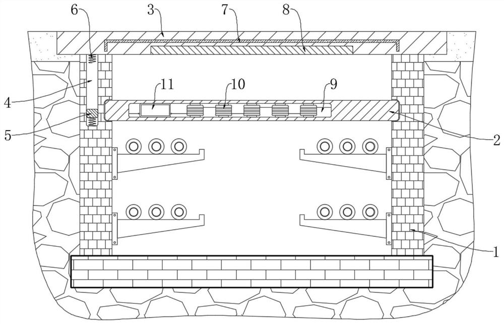
[0023] Refer figure 1 A compression-type cable duct component, comprising a cable trench symmetrically two side panels 1, the two side panels 1 on a common support plate 3 ditch, trench cover 3 is flush with the road surface, the trench lower surface of the cover plate 3 provided with a magnetic insert 8, wherein said one side plate defines a guide rail 4, the guide rail 4 is provided around the outer lead wire, said top and bottom slide 4 are reciprocally welded spring 6 is fixed, the two shuttle spring upright 5 has a magnetic stripe, stripe 5 slidably up and down between the guide rail 4 6, the shuttle spring 6 extended vertically slidable time stripe 5 At the same time, a collision can be avoided strong magnetic strip 5 and guide rails 4 or bottom wall occurs, resulting in loss of the magnetic stripe 5, between the two side plates fixed to a shield plate 2 is attached, is an insulating shield plate 2 made of a rigid material, said protective panel of said circuit module 2 defi...

Embodiment 2

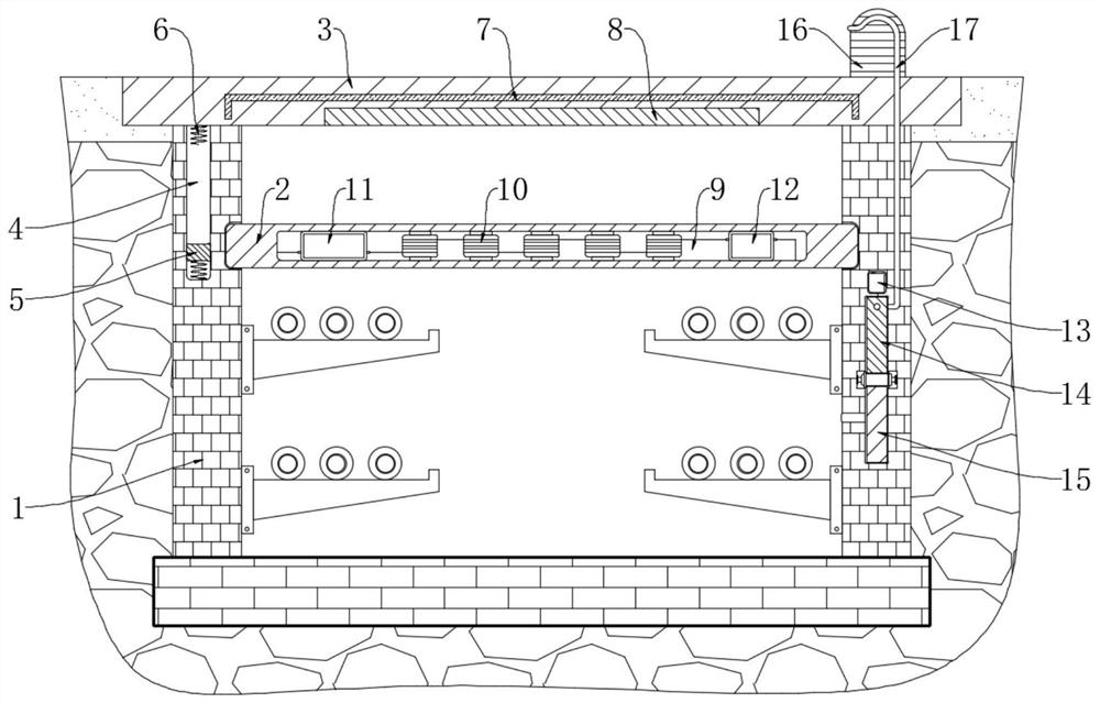
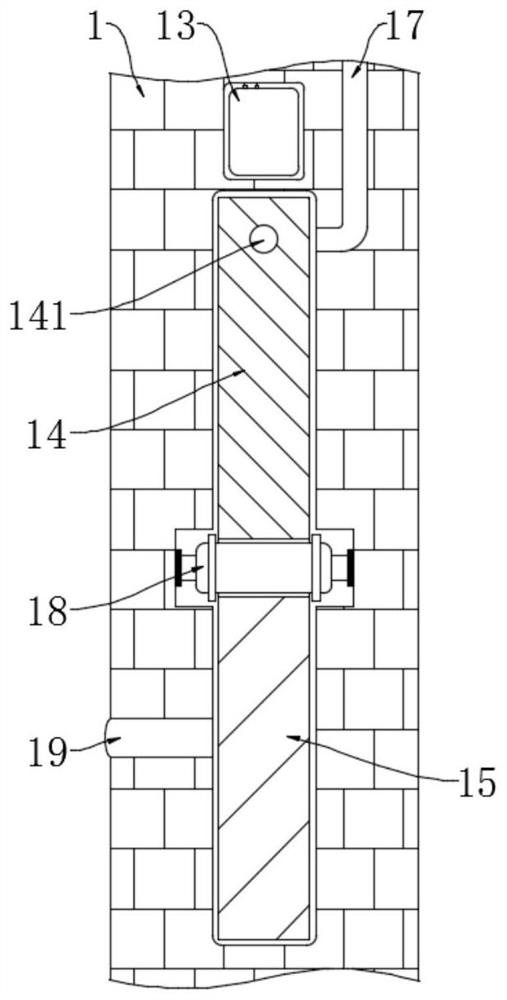
[0028] Refer Figure 2-4 The present embodiment is different from Embodiment 1 in that: a further side plate 1 is provided with warning means, the warning means comprises a side opening within a circular groove 21 through a rotating shaft 18 rotatably mounted within the circular groove 21 has a ferromagnetic plate 15, the ferromagnetic plate 15 is fan-shaped and the inner side wall of the circular groove 21 of the sealing slide contact, the circular groove 21 is fixed with a first fixing plate 14 and the second fixing plate 20, and the first and the second fixing plate 14 is fixed the upper plate 20 are respectively attached to first check valve 141 and the dust valve 201, the communication between the interior of the circular groove 21 and the cable channel has an intake pipe 19 and intake pipe 191 is attached to the third check valve 19.

[0029] In this embodiment, the warning means further comprises a groove and the cover plate 3 is fixedly connected to the warning device 16, t...


PUM


Abstract

The invention discloses a component-force compression-resistant cable trench, which comprises two side plates symmetrically distributed in the cable trench. The two side plates jointly support a trench cover plate, and the lower surface of the trench cover plate is embedded with a A magnetic plate is provided, and a slideway is opened in one of the side plates, and a wire is wound around the outside of the slideway. Reciprocating springs are fixedly welded on the top and bottom of the slideway, and between the two reciprocating springs A magnetic strip is placed vertically, and a protective plate is fixedly installed between the two side plates, and a circuit module and a plurality of solenoids are arranged inside the protective plate, and the circuit module is electrically connected with a wire. The invention transmits the pressure on the middle part of the trench cover to the protective plate, thereby improving the compressive capacity of the trench cover, and does not need a complicated frame structure to reinforce the trench cover, saving the inner space of the cable trench.

Description

Technical field [0001] The present invention relates to the technical field of electrical equipment, particularly to a compression force component cable trench. Background technique [0002] Common underground duct structure cable trench, cable ducts are mounted a plurality of cable holder, the cable may be arranged in layers is placed so that the cable laying more regular, above the cable channel be closed by a trench cover, the trench cover may be overhaul board open to facilitate staff access cable channel. [0003] Common trench cover for the pouring of concrete, with a certain strength, usually located on both sides of the road, can be used as a sidewalk, but compared to the normal terms of pavement, trench cover bearing capacity of poor, can not be used as a traffic lane Some drivers for quick overtaking or convenient Gasser, often ignoring the warning signage, secretly traveling on trench cover, causing structural damage trench cover appearance, and internal cable channel ...

Claims


Application Information

Patent Timeline
Patent Type & Authority Patents(China)
IPC IPC(8): H02G9/02G08B3/10H02K35/02H05K9/00
CPCH02G9/02G08B3/10H02K35/02H05K9/0098
Inventor 孙亚林王利利
Owner SHANGHAI MUNICIPAL ELECTRIC POWER CO
Why Eureka
Try Eureka