
Magnetic coupling mechanism suitable for wireless power transmission between rocket and ground and design method

A technology of wireless energy transmission and magnetic coupling, applied in transformer/inductor components, inductance/transformer/magnet manufacturing, preventing/reducing unwanted electric/magnetic effects, etc., can solve the problem that the coil cannot be well adapted to the rocket Issues such as the particularity of space structure, transmission distance and transmission efficiency requirements, to achieve good mutual inductance and coupling degree, stable transmission, and reduced impact

Pending Publication Date: 2020-12-22
TIANJIN POLYTECHNIC UNIV
View PDF4 Cites 0 Cited by
  • Summary
  • Abstract
  • Description
  • Claims
  • Application Information

AI Technical Summary

Problems solved by technology

[0005] The purpose of the present invention is to provide a magnetic coupling mechanism and design method suitable for wireless power transmission between rockets and the ground, to solve the problem that the existing coils cannot well adapt to the particularity of the space structure of the rocket, and its impact on the transmission distance and Transmission Efficiency Requirements

Method used


Image

  • Magnetic coupling mechanism suitable for wireless power transmission between rocket and ground and design method
  • Magnetic coupling mechanism suitable for wireless power transmission between rocket and ground and design method
  • Magnetic coupling mechanism suitable for wireless power transmission between rocket and ground and design method

Examples


Embodiment Construction

[0034] The solutions of the present invention will be further described below in conjunction with the accompanying drawings and specific embodiments.

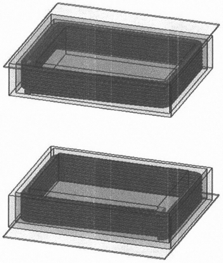
[0035] like figure 1 It is a magnetic coupling mechanism suitable for wireless power transmission between rockets and the ground. The main body of the mechanism includes two parts: a transmitting end and a receiving end. The transmitting end part is composed of a helical transmitting coil, a transmitting end ferrite and a transmitting coil shield; the receiving end part is composed of a helical receiving coil, a receiving end ferrite and a receiving coil shielding device.

[0036] At the transmitting end, the transmitting coil uses a helical coil as the coupling mechanism, which is rectangular in shape and is in a horizontal position. The transmitting coil is in the shape of an upper opening. The coil is wound with Litz wire, and its magnetic core is made of Mn-Zn ferrite material. The size of the coil is 20cm×15cm×6cm, the pi...


PUM


Abstract

The invention discloses a magnetic coupling mechanism suitable for wireless power transmission between a rocket and the ground. Th mechanism is characterized in that a mechanism main body comprises atransmitting end and a receiving end, and the transmitting end comprises a spiral transmitting coil, a transmitting end ferrite and a transmitting coil shielding device; and the receiving end comprises a spiral receiving coil, a receiving end ferrite and a receiving coil shielding device. Compared with a traditional magnetic coupling mechanism, the magnetic coupling mechanism meets the requirements of a rocket ground wireless power supply system for the transmission distance and the transmission power, has a good size to adapt to the space structure requirement of the bottom of a rocket, and can provide good mutual inductance capacity and coupling degree; in addition, the influence of coil magnetic field distribution on sensitive elements in the rocket and a human body is reduced to a certain extent, and therefore efficient, safe and stable transmission is achieved.

Description

technical field [0001] The invention relates to the field of wireless power transmission, in particular to a magnetic coupling mechanism and design method suitable for wireless power transmission between a rocket and the ground. Background technique [0002] Wireless power transmission technology transmits electrical energy from the transmitting end to the receiving end in the form of electrical isolation through high-frequency electromagnetic fields, electromagnetic waves, lasers, microwave methods, and ultrasonic methods. Compared with the traditional way of transmitting electrical energy through wires and metal contacts, wireless power transmission technology spans a certain distance, enabling electrical energy to be transmitted from the power supply end to the load end without electrical direct contact, which not only provides extremely flexible The wireless power transmission method can realize the efficient transmission and utilization of electric energy. [0003] The...

Claims


Application Information

Patent Timeline
Patent Type & Authority Applications(China)
IPC IPC(8): H02J50/10H02J50/12H02J50/70H01F27/28H01F27/36H01F38/14H01F41/00H01F41/02H01F41/04G06F30/17
CPCH02J50/10H02J50/12H02J50/70H01F38/14H01F27/28H01F27/2823H01F27/2885H01F27/36H01F41/00H01F41/02H01F41/04G06F30/17
Inventor 李颖牛萍娟刘宝丹隋宇李名洋
Owner TIANJIN POLYTECHNIC UNIV
Learn More