Automatic displacement type thigh muscle relaxing machine
A muscle relaxation and displacement technology, applied in vibration massage, roller massage, physical therapy, etc., can solve problems such as reducing massage comfort, achieve the effect of reducing operation difficulty, increasing the force bearing area, and ensuring comfort
- Summary
- Abstract
- Description
- Claims
- Application Information
AI Technical Summary
Problems solved by technology
Method used
Image
Examples
Embodiment approach 1
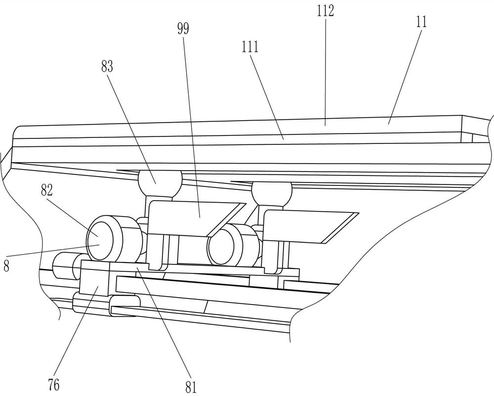
[0027] An automatic displacement type thigh muscle relaxation machine, such as Figure 1-2 As shown, including bracket 1, seat plate 2, back plate 4, control panel 5, LCD display screen 6, moving mechanism 7 and massage mechanism 8, the top of bracket 1 is connected with seat plate 2, and the right side of the top of seat plate 2 is connected with The backboard 4 is connected with a control panel 5 on the front side of the backboard 4 , an LCD display screen 6 is installed on the left side of the control panel 5 , a moving mechanism 7 is installed on the top of the bracket 1 , and a massage mechanism 8 is installed on the moving mechanism 7 .
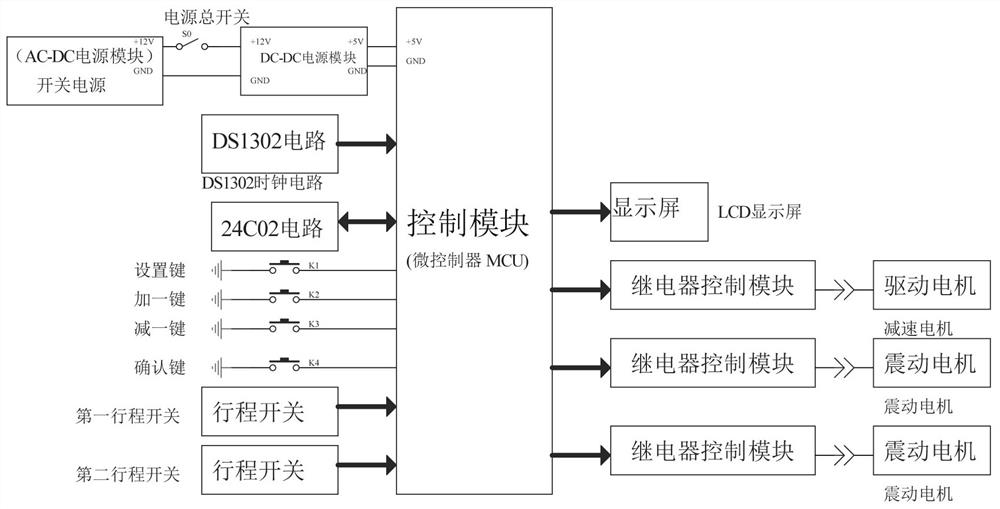
[0028] When it is necessary to massage the thigh, people press the main power switch to turn on the device, and then set the running time of the moving mechanism 7 and the massage mechanism 8 through the confirmation button, the setting button, the plus one button and the minus one button according to the actual situation. , press the s...
Embodiment approach 2
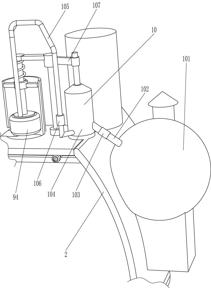
[0034] On the basis of Embodiment 1, such as Figure 2-4 As shown, it also includes a lubricating mechanism 9. The lubricating mechanism 9 includes a mounting pipe 91, a guide sleeve 92, a second guide rod 93, a sponge sleeve 94, a connecting rod 95, a spring 96, a sliding rod 97, a contact wheel 98 and a wedge plate 99. Mounting pipes 91 are embedded in the front and rear sides of the right side of the top of the seat plate 2. The two mounting pipes 91 are located on the right side of the backing plate 4. The sleeve 92 is slidably provided with a second guide rod 93 , the bottom end of the second guide rod 93 is connected with a sponge sleeve 94 , the top end of the second guide rod 93 is connected with a connecting rod 95 , and a spring is connected between the connecting rod 95 and the guide sleeve 92 96, the spring 96 is sleeved on the second guide rod 93, the two connecting rods 95 are connected with sliding rods 97, the two sliding rods 97 are slidably penetrated through...
PUM
 Abstract
Description
Claims
Application Information
 - R&D
- Intellectual Property
- Life Sciences
- Materials
- Tech Scout
- Unparalleled Data Quality
- Higher Quality Content
- 60% Fewer Hallucinations
Browse by: Latest US Patents, China's latest patents, Technical Efficacy Thesaurus, Application Domain, Technology Topic, Popular Technical Reports.
© 2025 PatSnap. All rights reserved.Legal|Privacy policy|Modern Slavery Act Transparency Statement|Sitemap|About US| Contact US: help@patsnap.com


