Soil remediation device

A technology of soil remediation and remediation solution, applied in the field of soil remediation devices, can solve the problems of incomplete soil remediation and no function of removing impurities, etc.

Inactive Publication Date: 2020-12-25
卢超
View PDF0 Cites 3 Cited by
  • Summary
  • Abstract
  • Description
  • Claims
  • Application Information

AI Technical Summary

Problems solved by technology

[0003] In the process of soil remediation, the soil needs to be broken first, and the soil is often mixed with some impurities such as gravel and metal. The soil remediation devices currently on the market do not have the function of removing impurities, so that the soil cannot be completely recovered. repair

Method used


Image

  • Soil remediation device
  • Soil remediation device
  • Soil remediation device

Examples


Embodiment 1

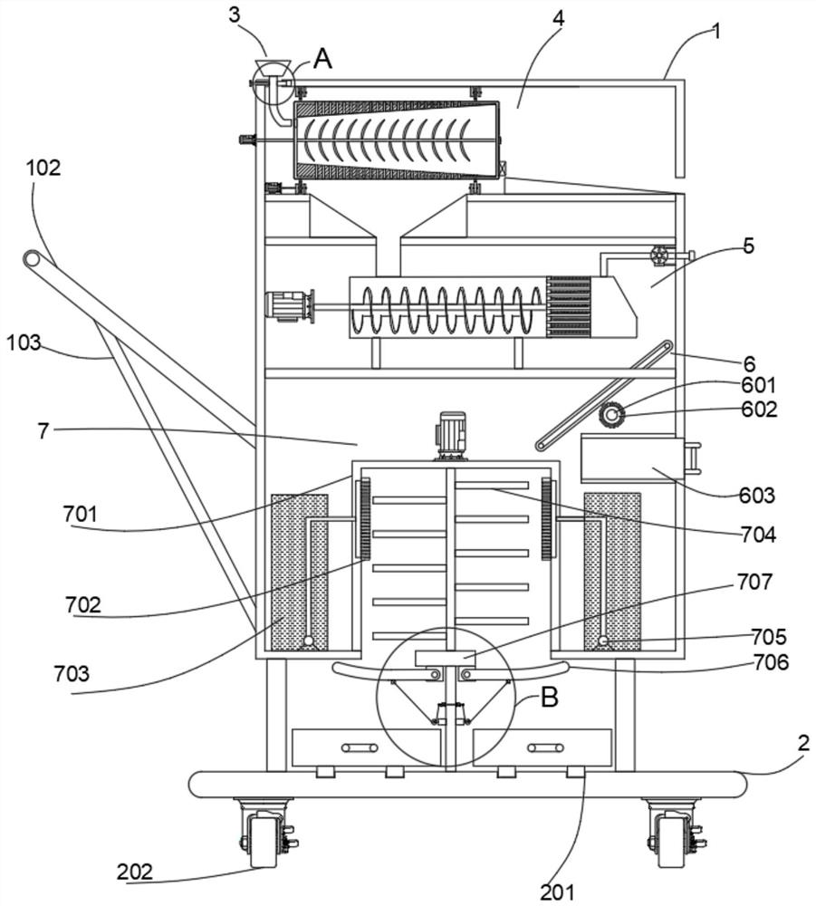
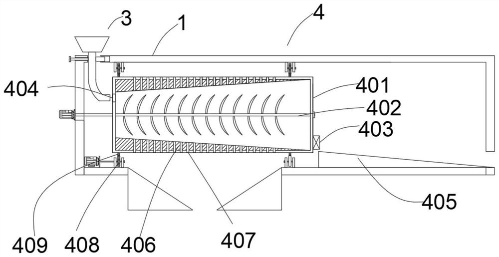
[0030] refer to Figure 1-6, a soil remediation device, comprising a box body 1 and a bottom plate 2, the box body 1 is a hollow structure, the box body 1 is fixedly connected with the bottom plate 2 through a first connecting rod, and the inner cavity of the box body 1 is A crushing mechanism 4, a thermal decomposition mechanism 5, a metal adsorption mechanism, and a repair fluid spraying mechanism 7 are arranged in sequence from top to bottom. The upper left side of the box body 1 is provided with a feeding mechanism, and the raw materials enter the box body 1 from the feeding mechanism. , firstly through the treatment of the crushing mechanism 4, the gravel slag in it is separated and the soil is crushed, and then through the treatment of the thermal decomposition mechanism 5, the organic matter adsorbed in the soil is volatilized, and then the metal in the soil is decomposed by the metal adsorption mechanism. Remove, and then spray the repair liquid in the soil through the...

Embodiment 2

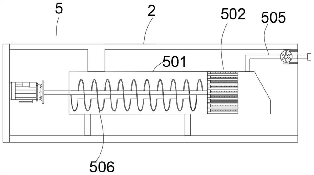
[0035] refer to figure 2 , a soil remediation device. This embodiment explains in detail the thermal decomposition mechanism 5 mentioned in Example 1. The thermal decomposition mechanism 5 includes a decomposition box 501, a decomposition ring 502 and a feeding dragon 506. The decomposition The upper side of the box 501 is provided with a second material inlet, and the feeding dragon 506 is arranged in the decomposition box 501 and is rotatably connected with it. A decomposition ring 502 is arranged in the decomposition box 501 on the right side of Jiaolong 506, and a plurality of soil circulation holes 503 are provided in the middle of the decomposition circle 502, and a heating rod 504 is arranged in the decomposition circle 502 around the soil circulation hole 503, The decomposition box 501 located on the right side of the decomposition circle 502 is connected to the outside air through an air outlet pipe 505, and an exhaust fan is arranged on the air outlet pipe 505; work...

Embodiment 3

[0037] refer to Figure 3-4 , a soil remediation device. This embodiment explains in detail the metal adsorption mechanism mentioned in Embodiment 1. The metal adsorption mechanism includes a transmission belt 6, a drive shaft 601 and a brush cover 602. The transmission belt 6 is arranged on On the lower right side of the thermal decomposition mechanism 5, the transmission belt 6 is provided with a magnetic attraction layer, and the transmission belt 6 is driven by a motor arranged on the outside of the casing 1, and the drive shaft 601 is arranged on the lower side of the transmission belt 6 and is connected with the casing The side walls of body 1 are rotationally connected, and the brush cover 602 is set in the outer ring of drive shaft 601; working principle: when the raw material falls on the transmission belt 6, the starting motor drives the transmission belt 6 to rotate counterclockwise, and at this time the drive shaft is rotated 601 drives the brush cover 602 to rotat...


PUM


Abstract

The invention discloses a soil remediation device which comprises a box body and a bottom plate. The box body is of a hollow structure. A crushing mechanism, a thermal decomposition mechanism, a metaladsorption mechanism and a remediation liquid spraying mechanism are sequentially arranged in an inner cavity of the box body from top to bottom. A feeding mechanism is arranged on the upper left side of the box body. The crushing mechanism comprises a crushing box, a stirring shaft, driving gears and gear rings. The crushing box is arranged in an inner cavity of the box body. The gear rings arearranged on the outer ring of the crushing box in a bilateral symmetry mode. A first transverse plate fixedly connected with the box body is arranged on the lower side of the crushing box. Two vertical plates are arranged on the upper side of the first transverse plate located on the lower side of the gear rings, the driving gears are rotatably connected between the vertical plates, and the driving gear located on the left side is driven by a driving motor arranged on the left side of the driving gear. By arranging the crushing mechanism, the thermal decomposition mechanism, the metal adsorption mechanism and the remediation liquid spraying mechanism, soil can be comprehensively remediated.

Description

technical field [0001] The invention relates to the technical field of soil restoration, in particular to a soil restoration device. Background technique [0002] Soil remediation is a technical measure to restore the normal function of polluted soil. In the soil remediation industry, there are more than one hundred kinds of existing soil remediation technologies, and there are more than ten commonly used technologies, which can be roughly divided into three methods: physical, chemical and biological; since the 1980s, many countries in the world, especially developed countries All countries have formulated and carried out contaminated soil treatment and remediation plans, so a new soil remediation industry has also been formed. [0003] In the process of soil remediation, the soil needs to be broken first, and the soil is often mixed with some impurities such as gravel and metal. The soil remediation devices currently on the market do not have the function of removing impur...

Claims


Application Information

Patent Timeline
Patent Type & Authority Applications(China)
IPC IPC(8): B09C1/06B09C1/08B09C1/00B02C13/06B02C13/286B02C13/30B02C13/28B03C1/20B03C1/30B65G45/18
CPCB02C13/06B02C13/2804B02C13/286B02C13/30B02C2013/28609B02C2013/28672B03C1/20B03C1/30B09C1/00B09C1/065B09C1/08B65G45/18
Inventor 卢超
Owner 卢超
Why Eureka
Try Eureka