Polisher spindle device and roll changing method
A spindle device and polishing machine technology, which is applied to surface polishing machine tools, grinding drive devices, grinding/polishing equipment, etc., can solve the problem that the aesthetics is difficult to meet customer needs, the polishing machine does not have the reciprocating vibration function, aluminum alloy Problems such as chromatic aberration on the surface of the plate can achieve the effect that high-frequency reciprocating vibration can achieve
- Summary
- Abstract
- Description
- Claims
- Application Information
AI Technical Summary
Problems solved by technology
Method used
Image
Examples
Embodiment 1
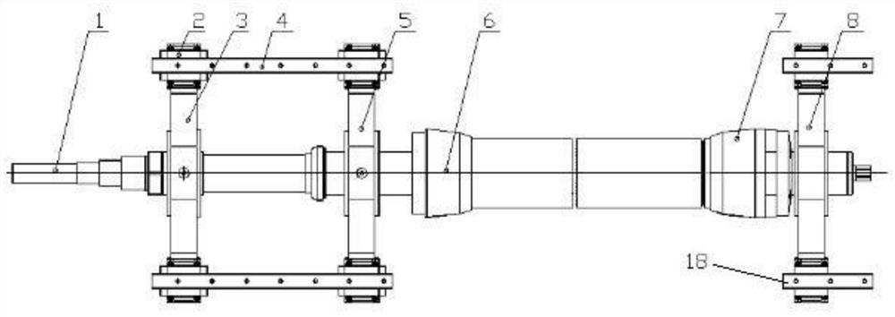
[0039] refer to figure 1 , is a schematic diagram of the structure of the spindle device of the present invention, a polishing machine spindle device, at least including the spindle body 1, and also includes a plurality of bracket mechanisms for supporting the spindle body 1, sliders 2, guide rails and polishing rollers 11, the sliders 2 are connected At the bottom of the support mechanism, the main shaft body 1 and the support mechanism are slidably connected to the guide rail through the slider 2, and the guide rail is connected to the frame of the polishing machine. A drive mechanism, and a second drive mechanism for driving the main shaft body 1 and the bracket mechanism to move axially along the main shaft body 1, the shaft side wall at the other end of the main shaft body 1 is connected with a support limit structure, and the support limit The structure is located between two adjacent support mechanisms, the polishing roller 11 is connected to the supporting and limiting...
Embodiment 2
[0043]Further, there are three support mechanisms, namely the first main shaft support 3, the second main shaft support 5 and the third main shaft support 8, and the shaft side of the main shaft body 1 between the second main shaft support 5 and the third main shaft support 8 A supporting and limiting structure is connected to the wall, and a polishing roller 11 is connected to the supporting and limiting structure.
[0044] Further, the first main shaft support 3, the second main shaft support 5 and the third main shaft support 8 are all bearing housings, the two ends of the bearing housings are connected with sliders 2, and the guide rails are provided with two rows and three bearings The seat is slidably connected on two rows of guide rails through the connected slider 2, and the main shaft body 1 is fixedly connected on three bearing seats.
[0045] Further described guide rails include a first guide rail 4 and a second guide rail 18, the first guide rail 4 and the second ...
Embodiment 3
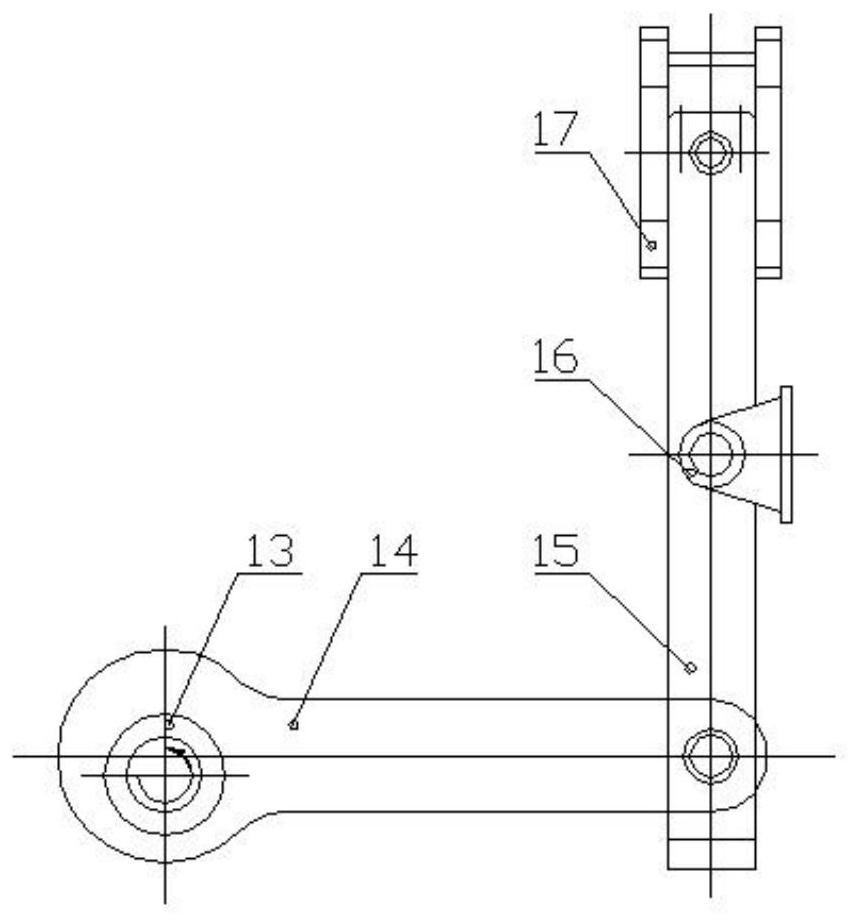
[0048] refer to image 3 , is a structural schematic diagram of Embodiment 3 of the driving mechanism of the present invention. The further described first driving mechanism is a first driving motor that drives the main shaft body 1 to rotate, and the second driving mechanism includes a first transmission rod, a second rotating Rod, toggle ring 17 and the second driving motor, the first transmission rod is an eccentric wheel connecting rod made up of an eccentric wheel 13 and a connecting rod 14, and the second rotating rod is a shift fork 15 of a "Y" type structure, so The eccentric wheel 13 at one end of the connecting rod of the eccentric wheel is connected to the second drive motor, the connecting rod 14 at the other end of the connecting rod of the eccentric wheel is hinged with the end of the "Y" structure shift fork 15, and the "Y" structure shift fork 15 The two ends of the fork are connected with the toggle ring 17, and the ring outer wall of the toggle ring 17 is pro...
PUM
 Abstract
Description
Claims
Application Information
 - R&D
- Intellectual Property
- Life Sciences
- Materials
- Tech Scout
- Unparalleled Data Quality
- Higher Quality Content
- 60% Fewer Hallucinations
Browse by: Latest US Patents, China's latest patents, Technical Efficacy Thesaurus, Application Domain, Technology Topic, Popular Technical Reports.
© 2025 PatSnap. All rights reserved.Legal|Privacy policy|Modern Slavery Act Transparency Statement|Sitemap|About US| Contact US: help@patsnap.com


