Supercharge Your Innovation With Domain-Expert AI Agents!

A kind of chamfering machine for ceramic ferrule production line and using method thereof

A ceramic ferrule and production line technology, which is applied in the field of chamfering machines for ceramic ferrule production lines, can solve the problems of low processing efficiency and long working hours, and achieve the effect of reducing chamfering man-hours and improving work efficiency

Active Publication Date: 2022-07-05
湖南中科光电有限公司
View PDF0 Cites 0 Cited by
  • Summary
  • Abstract
  • Description
  • Claims
  • Application Information

AI Technical Summary

Problems solved by technology

[0003] At present, when processing ceramic ferrules, it is necessary to chamfer them, but the general chamfering equipment is manually clamped and positioned before chamfering, the processing efficiency is not high, and the working hours are long

Method used


Image

  • A kind of chamfering machine for ceramic ferrule production line and using method thereof
  • A kind of chamfering machine for ceramic ferrule production line and using method thereof
  • A kind of chamfering machine for ceramic ferrule production line and using method thereof

Examples


Embodiment 1

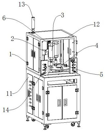
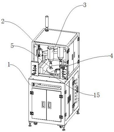
[0051] like Figure 1-Figure 7 As shown, a chamfering machine for a ceramic ferrule production line includes a clamping mechanism 5 for clamping the ceramic ferrule, a rotating mechanism 4 for rotating the ceramic ferrule, and a chamfering mechanism 3 for processing chamfering, A clamping mechanism 5 is installed on the rotating mechanism 4, a chamfering mechanism 3 is arranged on the upper side of the clamping mechanism 5, and the chamfering mechanism 3 is installed on the lifting mechanism 2. The power end of the lifting mechanism 2 is provided with a power mechanism 6, and the outside of the rotating mechanism 4 connect external institutions 1;

[0052] The external mechanism 1 includes a base 11, an outer box 12, a status light 13, and a control panel 14. An outer box 12 is installed on the upper end of the base 11, a status light 13 is installed on the upper end of the outer box 12, and a control panel is arranged at the front end of the outer box 12. 14. The vacuum clea...

Embodiment 2

[0060] like Figure 8 , the difference between this embodiment and Embodiment 1 is:

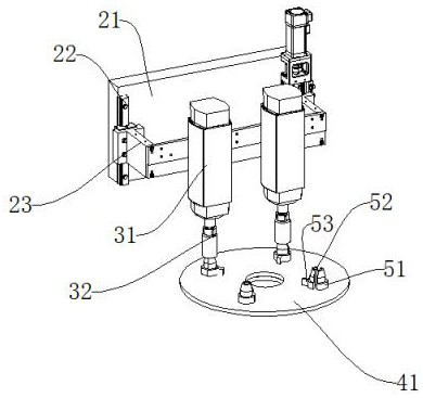
[0061] The power mechanism 6 includes a lifting cylinder 611 , a cylinder mounting seat 612 , and a connecting seat 613 . The lower end of the lifting cylinder 611 is connected to the cylinder mounting seat 612 , the cylinder mounting seat 612 is installed on the fixed seat 21 , and the power end of the lifting cylinder 611 is connected to the lifting seat through the connecting seat 613 23. When the chamfering motor 31 needs to be lifted and lowered, the lifting cylinder 611 is activated to drive the connecting seat 613, so that the lifting seat 23 can drive the chamfering motor 31 to lift and lower.

[0062] A method for using a chamfering machine for a ceramic ferrule production line, comprising the following steps:

[0063] a. Place the ceramic ferrule that needs to be chamfered between the fixed clamp block 51 and the movable clamp block 52 at the front end. At this time, the connecting...


PUM


Abstract

The invention discloses a chamfering machine for a ceramic ferrule production line and a method for using the same. The clamping mechanism is installed on the rotating mechanism, the chamfering mechanism is arranged on the upper side of the clamping mechanism, the chamfering mechanism is installed on the lifting mechanism, and the power end of the lifting mechanism is provided with a power A mechanism, the rotating mechanism is externally connected to an external mechanism. The invention utilizes the fixed clamping block and the movable clamping block to cooperate to clamp and cooperate with the transmission of the rotating disc, so that the ceramic ferrule can have a stable fixing force and can be quickly unloaded, and improve the work efficiency. The ceramic ferrule is processed to reduce the chamfering time of a single part, and at the same time, the multi-station processing is used to improve the work efficiency.

Description

technical field [0001] The invention relates to the field of ceramic ferrule production, in particular to a chamfering machine for a ceramic ferrule production line and a method for using the same. Background technique [0002] Optical fiber ceramic ferrule, also known as ceramic ferrule. A precisely centered cylinder in a fiber optic connector plug with a micro-hole in the center to hold the fiber. It is a high-precision special ceramic component made of nano-zirconia material through a series of formulas and processing, and its aperture and roundness error are 0.5 degrees. The prepared connector is a detachable and classified optical fiber active connector, which makes the connection and conversion scheduling of the optical channel more flexible, and can be used for debugging and maintenance of the optical channel system. [0003] At present, when processing ceramic ferrules, it is necessary to chamfer it, but the general chamfering equipment is manually clamped and posi...

Claims


Application Information

Patent Timeline
Patent Type & Authority Patents(China)
IPC IPC(8): B28D1/18B28D7/02B28D7/04
CPCB28D1/186B28D7/02B28D7/04
Inventor 卢立建
Owner 湖南中科光电有限公司
Features
  • R&D
  • Intellectual Property
  • Life Sciences
  • Materials
  • Tech Scout
  • Unparalleled Data Quality
  • Higher Quality Content
  • 60% Fewer Hallucinations
Learn More