
Unmanned vehicle, terminal point lateral steady-state control method thereof and electronic equipment

An unmanned vehicle, steady-state control technology, applied in the direction of the control device, etc., can solve the problems of preview distance attenuation, affecting the steady-state performance of parking at the end point, the number of preview points, and the lateral control oscillation of the end point attachment.

Pending Publication Date: 2020-12-25
北京易控智驾科技有限公司
View PDF1 Cites 4 Cited by
  • Summary
  • Abstract
  • Description
  • Claims
  • Application Information

AI Technical Summary

Problems solved by technology

In the process of implementing the technical concept of the present disclosure, the inventor found that the following problems exist in the prior art: when the vehicle approaches the end point of the track in the existing lateral stability control method at the end point of the preview point, as the distance from the end point of the track gets closer and closer near, the number of effective track points will continuously decrease to zero, which will cause the number of effective preview points to continuously decay to zero or the preview distance to continuously decay to a small value, due to the insufficient number of preview points or the limitation of preview distance Insufficient will cause oscillation phenomenon in the lateral control of the terminal attachment, affecting the steady-state performance of the terminal stop

Method used


Image

  • Unmanned vehicle, terminal point lateral steady-state control method thereof and electronic equipment
  • Unmanned vehicle, terminal point lateral steady-state control method thereof and electronic equipment
  • Unmanned vehicle, terminal point lateral steady-state control method thereof and electronic equipment

Examples


Embodiment Construction

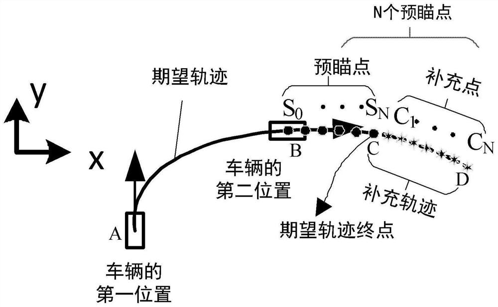
[0068] Embodiments of the present disclosure provide an unmanned vehicle and its endpoint lateral stability control method, and electronic equipment. By compensating the preview point after the endpoint of the desired trajectory, the moment before reaching the endpoint can be based on N previews Stable lateral control at the point, which solves the stability problem of lateral control at the end point, and improves the vehicle control performance.

[0069] In order to make the purpose, technical solutions and advantages of the present disclosure clearer, the present disclosure will be further described in detail below in conjunction with specific embodiments and with reference to the accompanying drawings.

[0070] The first exemplary embodiment of the present disclosure provides a terminal lateral stability control method of an unmanned vehicle.

[0071] figure 1 It is a flow chart of a terminal lateral stability control method of an unmanned vehicle according to an embodime...


PUM


Abstract

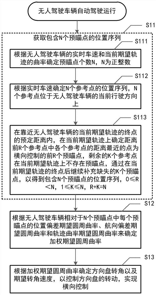
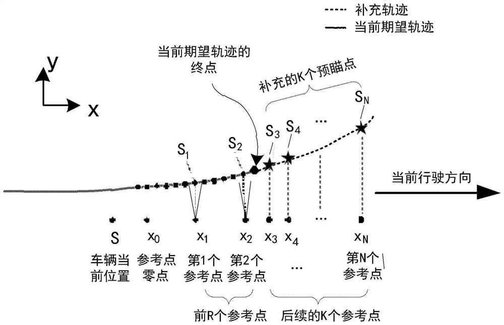
The invention discloses an unmanned vehicle, a terminal point lateral steady-state control method thereof and electronic equipment. The method comprises the following step that a position sequence containing N preview points is acquired; the number N of preview points is determined according to the real-time vehicle speed of the unmanned vehicle and the curvature of a current expected track; then,a position sequence of N reference points is determined according to the real-time vehicle speed, and the N reference points are located in the current driving direction of the unmanned vehicle; within a preset distance close to the terminal point of the current expected track of the unmanned vehicle, a point closest to each reference point in the first R reference points on the current expectedtrack is determined as the first R preview point for lateral control, the remaining K reference points do not have the preview points on the current expected track, and missing K preview points are continuously supplemented after the terminal point of the current expected track to obtain the position sequence containing the N preview points, wherein R is greater than or equal to 0 and less than N,K is greater than or equal to 1 and less than or equal to N, and R + K is equal to N. The stability of lateral control of the vehicle at the terminal point is ensured.

Description

technical field [0001] The disclosure belongs to the technical field of unmanned driving, and relates to an unmanned vehicle, a lateral stability control method for an end point thereof, and electronic equipment. Background technique [0002] The key technologies of intelligent driving involve many technical fields such as environmental perception, high-precision positioning, decision-making planning, and executive control. Executive control, as the bottom layer of the intelligent driving vehicle system, is directly related to the ultimate realization of the intelligent driving function. Vehicle motion control is the core part of executive control, generally divided into vehicle longitudinal control and lateral control. [0003] The lateral control of the vehicle is mainly to control the steering angle of the vehicle according to the expected path trajectory, so that the vehicle follows the expected trajectory. The most widely used in lateral control is preview tracking con...

Claims


Application Information

Patent Timeline
Patent Type & Authority Applications(China)
IPC IPC(8): B60W10/20B60W30/045B60W30/02B60W40/00B60W40/105B60W50/00B60W60/00
CPCB60W30/02B60W30/045B60W10/20B60W40/105B60W40/00B60W50/00B60W60/0025B60W2050/0043B60W2520/10B60W2710/20
Inventor 朱早贝吕金桐张磊
Owner 北京易控智驾科技有限公司
Learn More